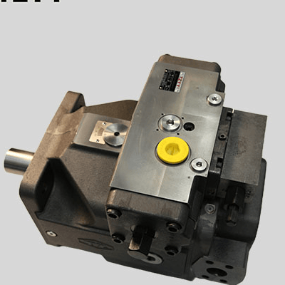
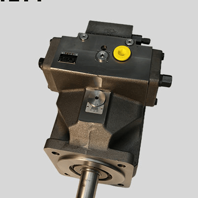
Suitable for: Open circuit hydraulic drive applications; hydraulic transmission fields requiring high pressure, heavy load, variable displacement, large flow, long service life and high reliability: steel metallurgy and forging presses; ceramic and refractory hydraulic presses; rubber vulcanizing machines and papermaking equipment; petroleum and petrochemical machinery; construction and mobile machinery; railway and shield tunneling machinery. Features: Compact structural design, light weight, low noise level. Pump flow is proportional to pump speed and displacement. Short control response time, long service life. Stepless displacement adjustment by adjusting the swashplate angle. Through-shaft design enables combination pumps. Rated working pressure 35MPa. Stackable design, excellent power/weight ratio. Excellent suction characteristics. Diverse control devices to meet system control requirements.
1/1


Piston Pump
EXW
$1,195.33-4,183.66 /unit
China
Taiyuan Heavy Machinery Hydraulic Industrial Park, Jingxi Avenue, Huitong Industrial Park, Jinzhong Development Zone, Shanxi Comprehensive Reform Demonstration Zone, Jinzhong City, Shanxi Province
+86 13835525180
+86 13835525180
qyue67885@gmail.com
Product Introduction
Product Parameters
Model Designation
|
XB |
01 |
V |
S |
O |
250 |
- |
01 |
/ |
R |
P |
P |
B |
13 |
NO0 |
- |
10 |
|
0 |
1 |
2 |
3 |
4 |
5 |
- |
6 |
/ |
7 |
8 |
9 |
10 |
11 |
12 |
- |
13 |
- Axial Piston Unit
|
Unit Type |
Code |
|
Swashplate axial piston pump |
XB |
- Product Series
|
Product Series |
Code |
|
Series 01 |
01 |
- Displacement Type
|
Displacement Type |
Code |
|
Variable displacement |
V |
- Type
|
Application Level |
Code |
|
Industrial grade |
S |
- Operating Mode
|
Operating Mode |
Code |
|
Open circuit |
O |
- Unit Size
|
Unit Displacement |
Code |
||||||
|
Displacement |
40 |
71 |
125 |
180 |
250 |
355 |
500 |
- Control Type (★ In stock ☆ In preparation - Not available)
|
Control Function |
40 |
71 |
125 |
180 |
250 |
355 |
500 |
Code |
|
Pressure Control (DR) |
★ |
★ |
★ |
★ |
★ |
★ |
★ |
01 |
|
Pressure Control (DRG) |
★ |
★ |
★ |
★ |
★ |
★ |
★ |
01G |
|
Flow Control (FR) |
★ |
★ |
★ |
★ |
★ |
★ |
☆ |
02 |
|
Pressure and Flow Control (DFR) |
★ |
★ |
★ |
★ |
★ |
★ |
☆ |
21 |
|
Dual Curve Power Control (LR2) |
★ |
★ |
★ |
★ |
★ |
★ |
☆ |
03 |
|
Electro-hydraulic Control (DFE1) |
★ |
★ |
★ |
★ |
★ |
★ |
一 |
04 |
|
Electronic Control (EO2) |
★ |
★ |
★ |
★ |
★ |
★ |
☆ |
05 |
7. Direction of Rotation
|
View Direction |
Direction of Rotation |
Code |
|
Viewed from shaft end |
Clockwise |
R |
|
Counter-clockwise |
L |
8. Unit Seals
|
Seal Type |
40 |
71 |
125 |
180 |
250 |
355 |
500 |
Code |
|
NBR (Nitrile rubber), shaft seal FKM (Fluororubber) |
★ |
★ |
★ |
★ |
★ |
★ |
★ |
P |
|
FKM (Fluororubber) / suitable for HFD operation |
★ |
★ |
★ |
★ |
★ |
★ |
★ |
V |
|
HFC special performance version |
一 |
一 |
★ |
★ |
★ |
★ |
一 |
F |
9.Unit Drive Shaft
|
Drive Shaft Type |
Code |
|
Parallel keyed shaft per DIN 6885 |
P |
|
Splined shaft per DIN 5480 |
Z |
10.Mounting Flange
|
Flange Type |
40 |
71 |
125 |
180 |
250 |
355 |
500 |
Code |
|
|
Per ISO 3019-2 (metric) |
4-hole |
★ |
★ |
★ |
★ |
★ |
★ |
一 |
B |
|
8-hole |
一 |
一 |
一 |
|
一 |
一 |
★ |
H |
|
11. Working Ports
|
Working Ports |
40 |
71 |
125 |
180 |
250 |
355 |
500 |
Code |
|
Ports B and S offset by 90°; auxiliary port B1 threaded connection |
★ |
★ |
★ |
★ |
★ |
★ |
一 |
13 |
|
Ports B and S offset by 90°; auxiliary port B1 flange connection |
★ |
★ |
★ |
★ |
★ |
★ |
★ |
25 |
12. Through-Shaft Drive
|
Through-Shaft |
Code |
|
Without auxiliary pump, without through-shaft drive |
NO0 |
|
With through-shaft drive for mounting axial piston units, gear or radial piston pumps |
K.. |
|
Universal through-shaft drive, adjustable |
U.. |
|
Flange (ISO 3019-2) Splined shaft coupling To be mounted |
|
|
125, 4-hole (ISO) 32x2x14×9g XB01VSO/G 40 |
31 |
|
140, 4-hole (ISO) 40x2x18x9g XB01VSO/G 71 |
33 |
|
160, 4-hole (ISO) 50x2x24x9g XB01VSO/G 125 |
34 |
12. Through-Shaft Drive
|
Flange Splined shaft coupling To be mounted |
|
|
160, 4-hole (ISO) 50x2x24x9g XB01VSO/G 180 |
34 |
|
224, 4-hole (ISO) 60x2x28x9g XB01VSO/G, XB01CSG 250 |
35 |
|
224, 4-hole (ISO) 70x3x22x9g XB01VSO/G, XB01CSG 355 |
77 |
|
315, 8-hole (ISO) 80x3x25x9g XB01VSO/G, XB01CSG 500 |
43 |
|
With through-shaft drive shaft, without coupling, without mating flange, closed with cover plate |
99 |
|
80, 2-hole 3/4'19-4(SAE A-B) A10VSO 18/31 |
B2 |
|
100, 2-hole 7/8'22-4(SAE B) A10VSO 28/31 |
B3 |
|
100, 2-hole 1'25-4(SAE B-B) A10VSO 45/31 |
B4 |
|
125, 4-hole 11/4'32-4(SAE C) A10VSO 71/31 |
B5 |
|
125, 4-hole 11/2'38-4(SAE C-C) A10VSO 100/31 |
B6 |
|
180, 4-hole 13/4'44-4(SAE D) A10VSO 140/31 |
B7 |
- Design Number
|
Design Number |
Code |
|
Series 10 |
10 |
Combination Pumps
1. For pump sizes 125 to 355, all through-shaft drives are supplied as universal through-shaft drive "U". The advantage of this is that it can be adjusted at a later stage. The through-shaft drive option can be converted simply by exchanging the mating flange and shaft coupling.
- The combination of several pumps can form independent circuits.
3. If two XB01VSO pumps are used in combination, the two order models are connected with "+": model of the first pump + model of the second pump.
Example: XB01VSO250-01/RPPB13U34-10+XB01VSO180-01/RPZB13NO0-10