Maui County Water Department Installs 105–141 kW Photovoltaic Arrays on Reservoir Roof
en.Wedoany.com Reported - The Maui County Department of Water Supply has installed low-tilt, non-penetrating ballasted photovoltaic arrays on the roof of a circular concrete storage reservoir. The arrays have a DC power output of approximately 105 to 141 kilowatts, and the electricity generated is used directly to offset the electrical load of the reservoir facility. The project was delivered by Johnson Controls as the contractor.
Pumping is typically the primary electrical load for drinking water utilities. The U.S. Environmental Protection Agency (EPA) notes that about 80% of municipal water treatment and distribution costs go to electricity; energy is also often the largest controllable operating expense, accounting for roughly 25% to 30% of operations and maintenance (O&M) costs. Flat, sunny idle land near load facilities is uncommon, especially on islands.
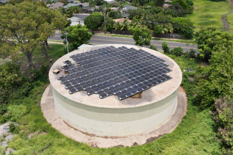
These arrays do not penetrate the roof; they are ballasted, secured by weight rather than fasteners. The solar modules themselves are relatively light, and the key factor is how much ballast the tank can support, which depends primarily on seismic behavior rather than the roof itself. These reservoirs are decades old, and before installation, structural engineers predetermined their capacity based on original drawings or on-site assessments.
The photovoltaic modules and racking systems are rectangular, while the reservoir roof is circular. The arrays must be arranged within the inner circular area, set back from the curved edge, and avoid access hatches, vents, and inspection points that remain in use. Maximizing the area within the circle while maintaining perimeter setbacks and exclusion zones is the core layout challenge for tank-mounted systems, which is why these arrays appear as dense rectangular zones with recessed edges.

The layout must also meet roof photovoltaic fire access requirements. Per Section 1204.3 of Chapter 12 of the 2018 International Fire Code, which addresses pathways on flat roofs, the design maintains a clear perimeter pathway of at least four feet around the arrays and a four-foot clearance around each roof access hatch. The code's baseline perimeter requirement is six feet; under the exception in Section 1204.3.1, when any axis of the structure is 250 feet or less in length, the perimeter may be reduced to four feet. This project qualifies for that exception, reclaiming usable roof area while preserving access.
The tanks are tall and typically sit on high, open ground, resulting in significant wind loads. Ballasted arrays rely on weight to resist uplift, but adding ballast amplifies lateral forces under seismic loads, making mass a double-edged sword. The water in the tank reacts during an earthquake and generates its own lateral forces, which makes the ballast-versus-seismic balance tighter on tanks than on ordinary buildings: before any ballast is added, the tank already bears heavy seismic demands. The limiting constraint is not the roof's gravity load capacity—the panels are light and largely replace the pedestrian live load the roof was originally designed to support; the constraint is how much additional seismic load the ballast can add to a tank already stressed by stored water. Wind and seismic forces must be solved simultaneously: ballast sizing for wind uplift is determined per ASCE 7, the American Society of Civil Engineers load standard, then the added weight is checked to ensure it does not push the seismic case past its limit, with iterative coordination between the two. Low-tilt modules capture less wind and correspondingly require less ballast.
Photovoltaic arrays can last for decades, and the reservoirs below are expected to serve for even longer; they cannot fail due to the solar installation. The EPA regards open access hatches and damaged vent screens as sanitary risks for finished water storage, and a poorly arranged roof array could obstruct or damage these components. Therefore, access hatches, vents, and inspection points remain clear, and the layout preserves pathways for future internal inspections and recoating. Since flat roofs accumulate water, modules and conduits are elevated to avoid low-lying areas.
Inverters, disconnects, and distribution panels are mounted on separate racks on the ground beside the tank rather than on the tank wall, moving heavy equipment off the structure. Conductors routed along the wall are secured with anchors suitable for the tank's construction, with attachment methods matched to how the specific wall is built. Array output is delivered via cable to the ground-level inverters.
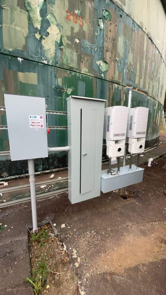
Reservoir roof photovoltaic installation is treated as a repeatable approach rather than a one-off project: converting infrastructure the utility already owns into distributed generation, offsetting most of the facility's electrical load, and reducing operating costs for critical water services. The execution standards are consistent across sites—starting with a structural assessment, using ballasted non-penetrating arrays, calculating wind and ballast as a coupled optimization problem, optimizing the array within the circular footprint, and treating the tank's own maintenance functions as a paramount requirement.
The broader takeaway is that the most valuable solar sites are sometimes already built. Reservoir roofs are not free land; they are constrained structures with strict rules. But for utilities with scarce land and heavy pumping loads, water storage assets can equally become the best places to generate the electricity that moves the water.
Related Products

G.652.D Wavelength-extended Non-dispersion Shifted Single-mode Optical Fiber
HONGAN GROUP CO., LTD.
IGBT Hydrogen Production Power Supply - High Power Air Cooling
Beijing Zhengzhuo Engineering Technology Co., Ltd.
0.66kV Power Supply Instrument Transformer
Guangdong Sihui Instrument Transformer Works Co., Ltd.
Forest and Grassland Heat Source Infrared Monitor
China Huayun Meteorological Technology Group Co., Ltd.
Perfluorinated Ionic Membrane-CM-10N Series Membrane
Guizhou Juneng Century Technology Co., Ltd