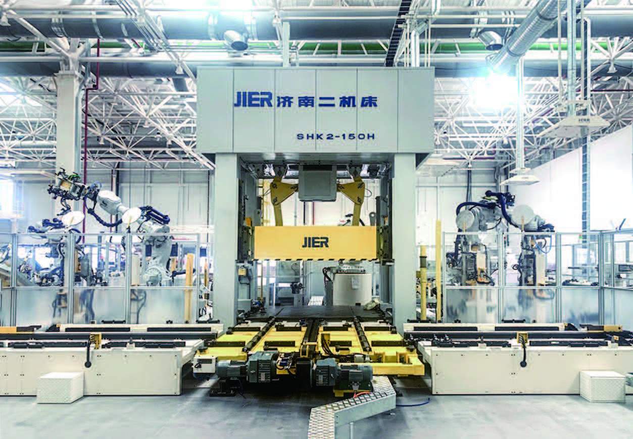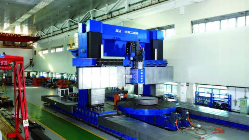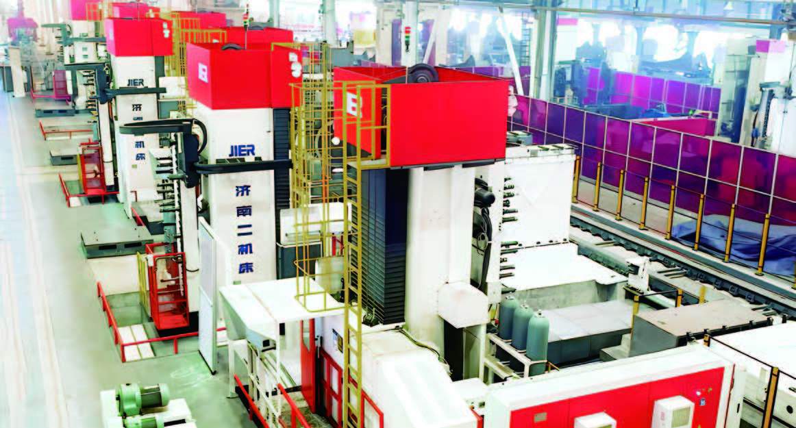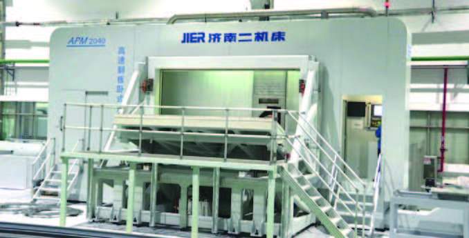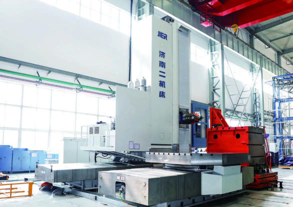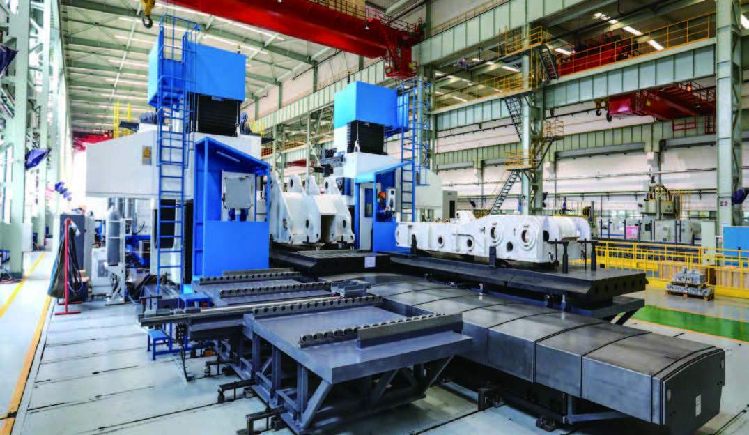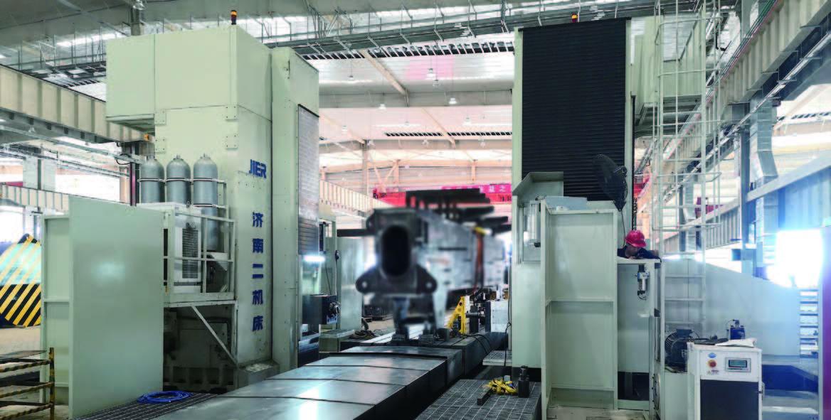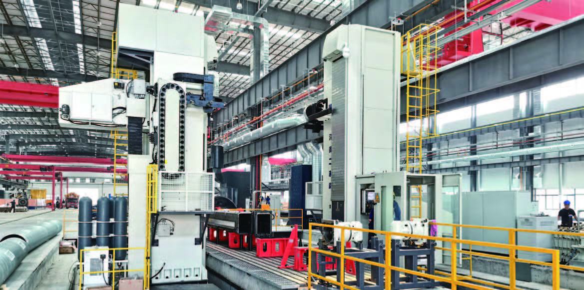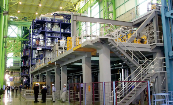


■ Structural Performance Features
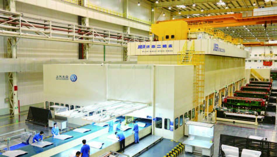
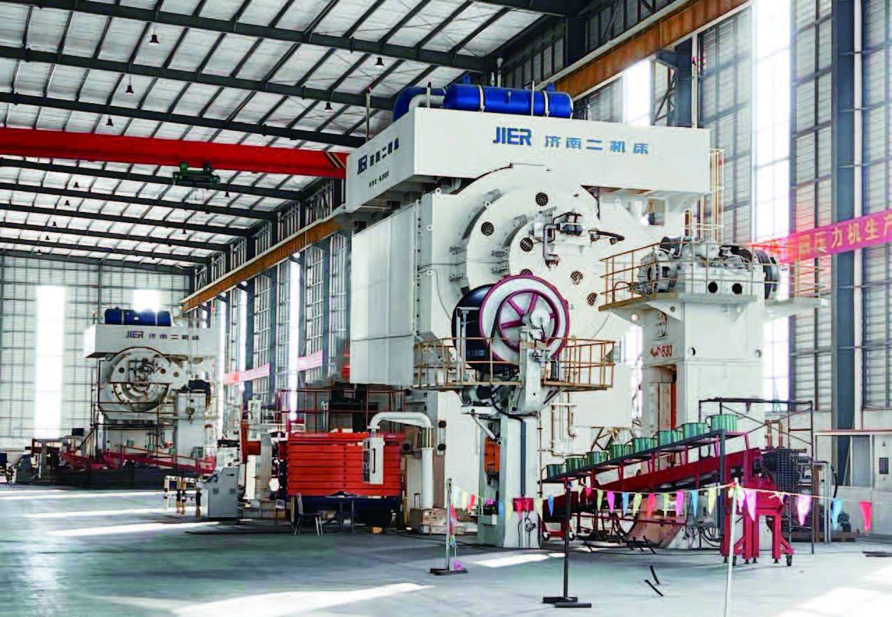
- The entire machine adopts a cast steel or welded frame, pre-tensioned by hydraulic tie rods, offering high rigidity;
- The connecting rod adopts a double-support structure, providing strong resistance to eccentric loads;
- The transmission adopts a large-inertia design, delivering high forging energy;
- The frame guideways adopt X-type guideways with wide guide surfaces and extra-long guidance, ensuring high overall precision;
- Equipped with hydraulic upper and lower ejectors;
- Configured with mechanical upper and lower die clamps;
- Optional die-change lifting platform, die lubrication coolant recovery and recycling system, and dust removal system;
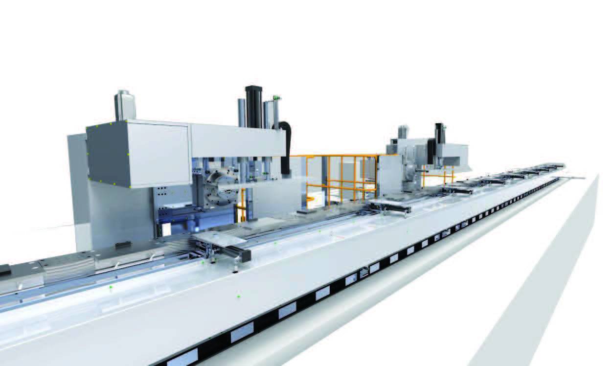
- Can be adapted to a walking beam or robot for automated forging.
■ Walking Beam Structural Performance
- Ten-axis drive, with six axes on the unloading side and four axes on the loading side;
- Maximum transfer rate/spm: 20, repeat positioning accuracy ±0.25mm;
- Maximum stroke/mm: feed 600, lift 150, clamp 200;
- Number of stations: 3-5;
- Intermediate beam replacement is automatic or manual;
- Custom-designed grippers.
■ Application Fields
- In the automotive industry, it is used to manufacture key components such as engine crankshafts, connecting rods, and wheel hubs. These forgings require high strength and good mechanical properties, which the hot die forging press can satisfy.
- In the aerospace field, it is used to produce components such as aircraft engine blades and landing gear parts, which demand extremely high material performance and precision.
- In the energy industry, it manufactures key components for petroleum machinery and wind power equipment, such as oil drill pipes and wind turbine tower flanges.
■ Main Technical Parameters
| Item | Unit | 165000 | 125000 | 80000 | 63000 | 40000 | 25000 | 16000 |
|---|---|---|---|---|---|---|---|---|
| Nominal Pressure | kN | 165000 | 125000 | 80000 | 63000 | 40000 | 25000 | 16000 |
| Slide Strokes per Minute | SPM | 32 | 35 | 40 | 40 | 50 | 70 | 85 |
| Maximum Production Rate | SPM | 5 | 6 | 12 | 12 | 14 | 20 | 24 |
| Maximum Die Height | mm | 2120 | 1817 | 1603 | 1363 | 1210 | 1012 | 860 |
| Die Height Adjustment | mm | 20 | 17 | 13 | 13 | 10 | 12 | 10 |
| Slide Stroke | mm | 600 | 520 | 480 | 460 | 400 | 350 | 300 |
| Slide Bolster Size: FR×LR | mm | 3450×2650 | 2680×2460 | 2350×1900 | 1850×1900 | 2000×1470 | 1450×1500 | 1400×1120 |
| Bolster Size: FR×LR | mm | 3500×2650 | 3100×2150 | 2300×2100 | 1950×2100 | 1620×1680 | 1500×1500 | 1300×1260 |
| Upper Ejector | Type | Hydraulic | Hydraulic | Hydraulic | Hydraulic | Hydraulic | Hydraulic | Hydraulic |
| Force kN | 350 | 350 | 300 | 300 | 200 | 150 | 80 | |
| Stroke mm | 60 | 60 | 60 | 60 | 40 | 40 | 37 | |
| Lower Ejector | Type | Hydraulic | Hydraulic | Hydraulic | Hydraulic | Hydraulic | Hydraulic | Hydraulic |
| Force kN | 750 | 750 | 700 | 700 | 600 | 500 | 240 | |
| Stroke mm | 40-160 | 40-160 | 40-150 | 40-150 | 0-120 | 0-80 | 0-37 |