

Overview
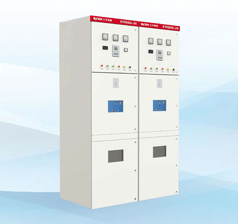
The KYN28A-24 armored removable AC metal-enclosed switchgear (hereinafter referred to as switchgear) is suitable for indoor three-phase 50/60Hz, rated voltage 24kV power systems. It is mainly used in power plants, substations, industrial and mining enterprises, and high-rise buildings for receiving and distributing electrical energy, as well as controlling, protecting, and monitoring circuits.
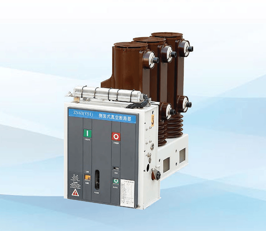
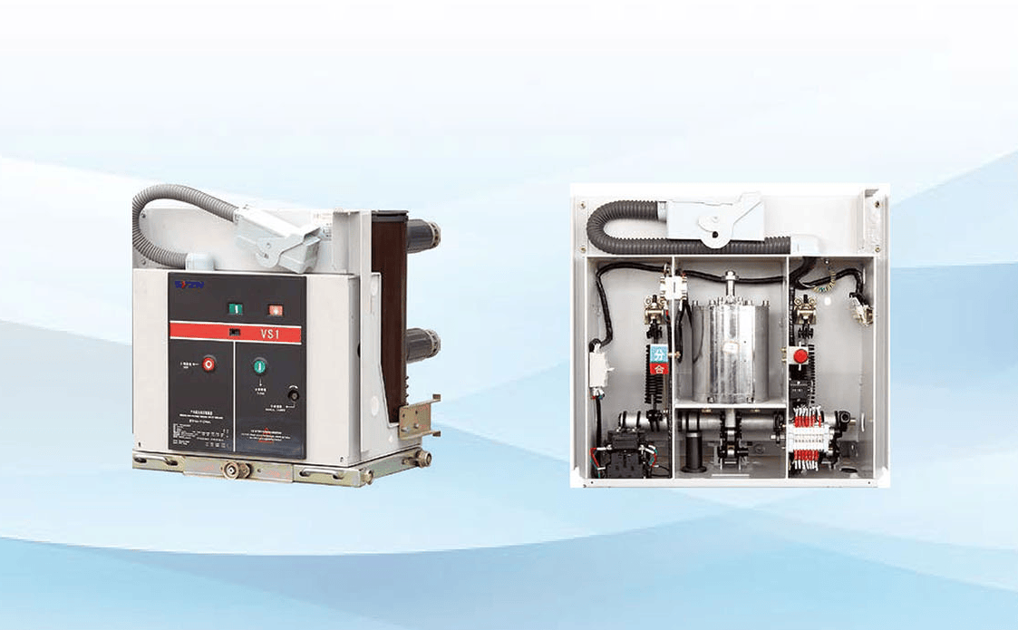
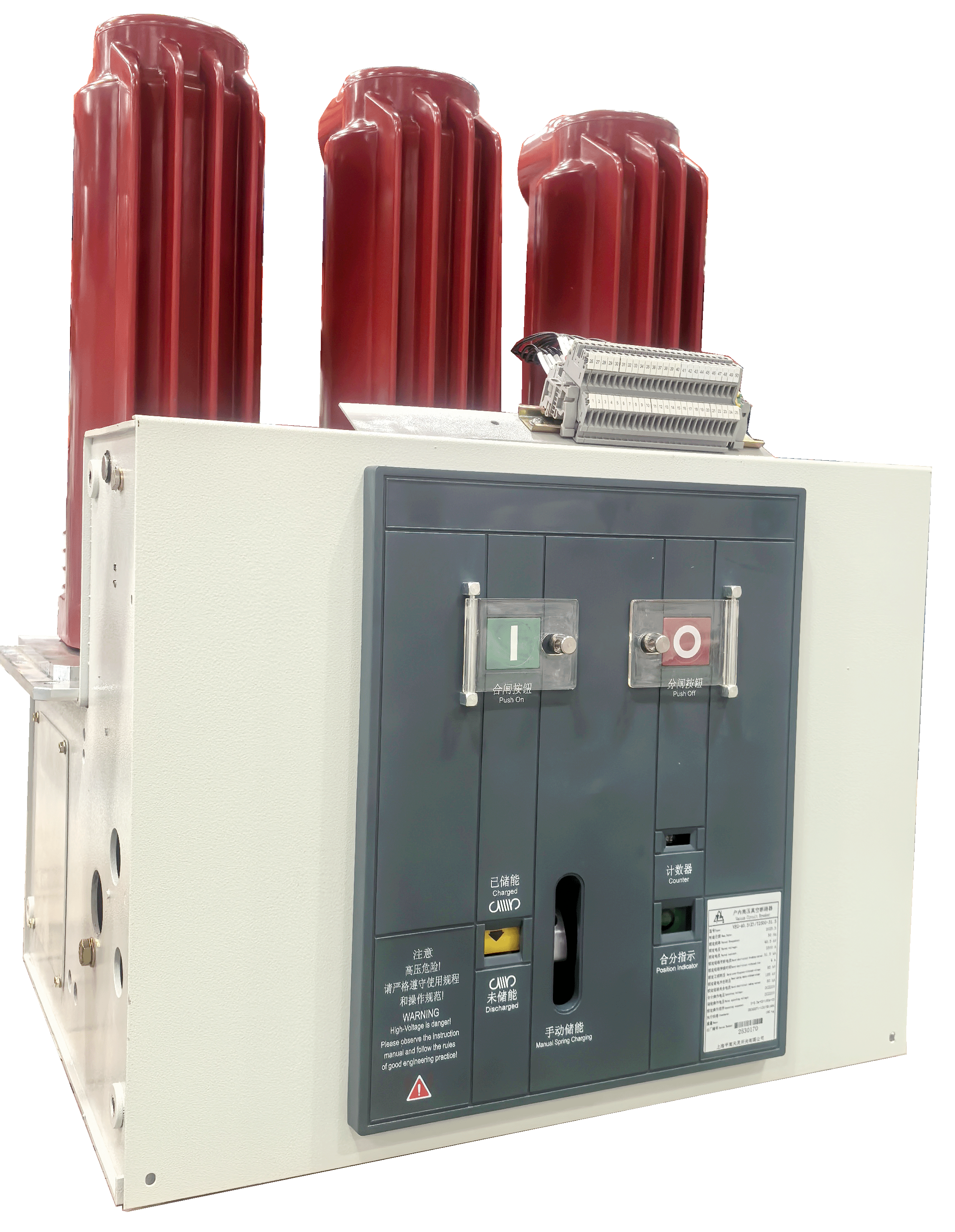
The KYN28A-24 switchgear features various anti-misoperation functions, including preventing the movement of the withdrawable truck under load, preventing the closing of the circuit breaker when the earthing switch is in the closed position, preventing the closing of the earthing switch when the circuit is energized, and preventing accidental entry into energized compartments. The switchgear is equipped with high-performance VS1 and VN2 series mid-mounted high-voltage AC vacuum circuit breakers and solid-sealed vacuum switches. The secondary circuit of the switchgear is equipped with advanced and reliable control and protection components; the busbars adopt heat-shrinkable insulating materials or epoxy-coated insulation measures, with optimized electrode shapes and a compact cabinet structure. This switchgear is a distribution device featuring advanced technology, stable performance, reasonable structure, ease of use, and safety and reliability.
Normal Service Conditions
1. Environmental conditions: Maximum temperature: +40℃, minimum temperature: -15℃, and the average value measured within 24h shall not exceed 35℃;
2. Humidity conditions are as follows: The average daily relative humidity shall not exceed 95%; the average monthly relative humidity shall not exceed 90%; the average daily water vapor pressure shall not exceed 2.2kPa; the average monthly water vapor pressure shall not exceed 1.8kPa;
3. Altitude shall not exceed 1000m;
4. The surrounding air is not significantly polluted by dust, smoke, corrosive or flammable gases, vapor, or salt spray;
5. Vibration or earth tremors from outside the switchgear and controlgear are negligible;
6. The amplitude of electromagnetic interference induced in the secondary system shall not exceed 1.6kV.
Special Service Conditions
When used under conditions exceeding the normal environmental conditions specified in GB/T11022, our company and the user may negotiate and reach an agreement on special operating conditions beyond normal operating conditions. To prevent condensation, the switchgear is equipped with heaters, which should be put into operation when the switchgear is in standby status. Attention should also be paid to putting the heaters into operation during normal operation of the switchgear.
Technical Parameters
Main Technical Parameters of Switchgear
| No. | Item | Unit | Parameter | ||||
| 1 | Rated voltage | kV | 24 | ||||
| 2 | Rated frequency | Hz | 50/60 | ||||
| 3 | Rated insulation level | Lightning impulse withstand voltage (peak) | kV | Between phases and to earth | 60 | Isolating distance | 79 |
| 1min power frequency withstand voltage (rms) | 125 | 145 | |||||
| Auxiliary control circuit power frequency withstand voltage | V | 2000 | |||||
| 4 | Rated current | A | 630,1250,1600,2000,2500,3150 | ||||
| 5 | Rated short-circuit breaking current | kA | 20 | 31.5 | |||
| 6 | Rated short-circuit making current (peak) | kA | 50 | 80 | |||
| 7 | Rated short-time withstand current (4s) | kA | 20 | 31.5 | |||
| 8 | Rated peak withstand current | kA | 50 | 80 | |||
| 9 | Rated voltage of auxiliary control circuit | V | DC or AC 110/220 | ||||
| 10 | Degree of protection | IP4X (IP2X when circuit breaker compartment door is open or compartment door) | |||||
| 11 | Overall dimensions (W×D×H) | mm | 800×1810×2380 | 1000×1810×2380 | |||
| 12 | Weight | Kg | 840~1440 | ||||
Note: The depth of the overhead incoming/outgoing line cabinet is 2360mm.
Main Technical Parameters of VS1-24, VN2-24 Vacuum Circuit Breaker
| No. | Item | Unit | Parameter | ||
| 1 | Rated voltage | kV | 24 | ||
| 2 | Rated insulation level | 1min power frequency withstand voltage (rms) | 60 | ||
| Lightning impulse withstand voltage (peak) | 125 | ||||
| 3 | Rated frequency | Hz | 50/60 | ||
| 4 | Rated current | A | 630,1250,1600,2000 | 630,1250,1600,2000,2500,3150 | |
| 5 | Rated short-circuit breaking current | KA | 20 | 31.5 | |
| 6 | Rated short-circuit making current | 50 | 80 | ||
| 7 | Rated short-time withstand current (4s) | 20 | 31.5 | ||
| 8 | Rated peak withstand current | 50 | 80 | ||
| 9 | Rated breaking current of single capacitor bank | A | 630 | ||
| 10 | Rated breaking current of back-to-back capacitor bank | 400 | |||
| 11 | Number of rated short-circuit breaking current operations | times | 50 | ||
| 12 | Mechanical life | 20000 | |||
| 13 | Rated operating sequence | O-0.3s-CO-180s-CO | |||
Technical Parameters of Spring Operating Mechanism
| No. | Item | Unit | Parameter | |
| 1 | Rated operating voltage | Closing trip coil | V | AC220,AC110,DC220,DC110 |
| Opening trip coil | ||||
| 2 | Operating current | Closing trip coil | A | AC220 or DC220 is 1.1 AC110 or DC10 is 3.1 |
| Opening trip coil | ||||
| 3 | Energy storage motor power | W | 80,100 | |
| 4 | Rated voltage of energy storage motor | S | AC220,AC110,DC220,DC110 | |
| 5 | Electric energy storage time | V | ≤10 | |
Structure and Working Principle
The KYN28A-24 switchgear consists of two main parts: the cabinet and the removable part (commonly known as the truck). The cabinet is divided by metal partitions into multiple functional compartments, such as the busbar compartment, circuit breaker compartment, cable compartment, and relay instrument compartment.
The removable part of the switchgear can be equipped with vacuum circuit breaker trucks, voltage transformer trucks, surge arrester trucks, isolation trucks, and fuse trucks.