
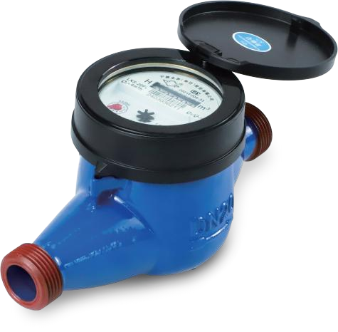
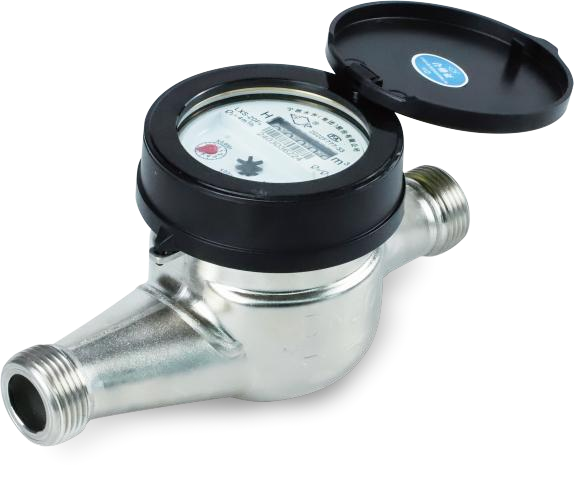
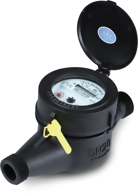
The economical water metering solution is a traditional water metering approach centered on mechanical water meters. Since the production and application of mechanical water meters began in the 1960s, continuous optimization and upgrades have been made in meter structure, materials, installation methods, and reading modes to adapt to market conditions and customer needs. With accurate metering as the core objective, it effectively manages residential water consumption.
1/4


Economical Water Metering Solution
Negotiable
China
No.355 Hongxing Road, Jiangbei District, Ningbo City, Zhejiang Province
+86-574-88195820
sales@nwmwatermeters.com
Product Introduction
Product Parameters
Technical parameters
Flow parameters
|
Caliber DN |
Q3 /Q1 |
Overload flow Q4 |
Common flow Q3 |
Demarcation flow Q2 |
Minimum flow Q1 |
Min Reading |
Max Reading |
|
m3 /h |
L/h |
m3 |
|||||
|
15 |
160 |
3.125 |
2.5 |
25.0 |
15.6 |
0.00001 |
999 999 |
|
125 |
32.0 |
20.0 |
|||||
|
100 |
40.0 |
25.0 |
|||||
|
20 |
160 |
5 |
4.0 |
40.0 |
25.0 |
||
|
125 |
51.2 |
32.0 |
|||||
|
100 |
64.0 |
40.0 |
|||||
|
25 |
160 |
7.875 |
6.3 |
63.0 |
39.4 |
||
|
125 |
80.6 |
50.4 |
|||||
|
100 |
100.8 |
63.0 |
|||||
|
32 |
160 |
12.5 |
10 |
100.0 |
62.5 |
||
|
125 |
128.0 |
80.0 |
|||||
|
100 |
160.0 |
100.0 |
|||||
|
40 |
160 |
20 |
16 |
160.0 |
100.0 |
9 999 999 |
|
|
125 |
204.8 |
128.0 |
|||||
|
100 |
256.0 |
160.0 |
|||||
|
50 |
160 |
31.25 |
25 |
250.0 |
156.3 |
||
|
125 |
320.0 |
200.0 |
|||||
|
100 |
400.0 |
250.0 |
|||||
Maximum allowable error: the maximum allowable error in the low area (Q1 ≤Q<Q2) is ± 5%; the maximum allowable error in the high area (Q2 ≤Q≤Q4) is ± 2%.
Appearance size
Rotor multi-beam wet water meter (liquid seal)
LXS-15F ~ 50F LXSL-15F ~ 32F
|
Caliber DN |
Long L |
Width B |
High H |
Connection mode |
Weight |
|
|
mm |
d |
D |
Kg |
|||
|
Horizontal |
||||||
|
15 |
165 |
92 |
108 |
R1/2 |
G3/4B |
1.2 |
|
20 |
195 |
92 |
108 |
R3/4 |
G1B |
1.3 |
|
25 |
225 |
99 |
116 |
R1 |
G1 1/4B |
1.8 |
|
32 |
230 |
99 |
116 |
R1 1/4 |
G1 1/2B |
1.95 |
|
40 |
245 |
124 |
154 |
R1 1/2 |
G2B |
3.65 |
|
50 |
280 |
165 |
179 |
① |
9.5 |
|
|
Vertical |
||||||
|
15 |
149 |
92 |
100 |
R1/2 |
G3/4B |
1.25 |
|
20 |
158 |
92 |
100 |
R3/4 |
G1B |
1.5 |
|
25 |
171 |
99 |
110 |
R1 |
G11/4B |
1.8 |
① Flange connection as per GB/T17241.6-2008/XG1-2011D = Φ165 D1 = Φ125
Note: The dimensions and weight are for reference only, and the actual product shall prevail.
Performance parameters
|
Temperature Class |
T30/T50 |
Flow field sensitivity level |
U0/D0 |
|
Maximum allowable pressure |
1.0MPa/1.6MPa |
Accuracy class |
Level 2 |
|
Pressure loss rating |
△p63 |
Other products from this supplier

Negotiable
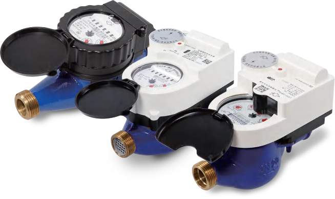
Decentralized Water Metering Solution – Smart Card Meter
Negotiable
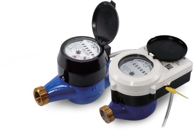
Decentralized Water Metering Solution – Wireless Remote Transmission
Negotiable
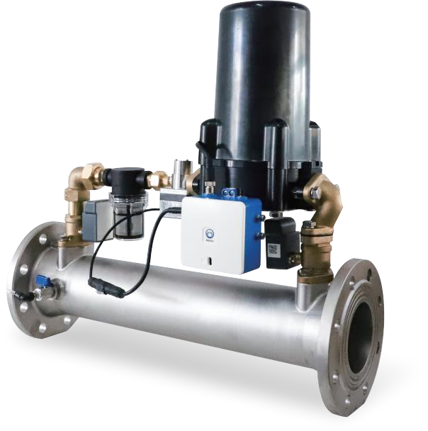
Centralized Water Metering Solution
Negotiable
Multi-parameter Water Quality Monitoring Instrument NWM-MW100

Negotiable
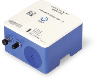
Real-time Data Monitoring Instrument NWM-D110
Negotiable
Wireless Data Monitoring Instrument NWM-K130
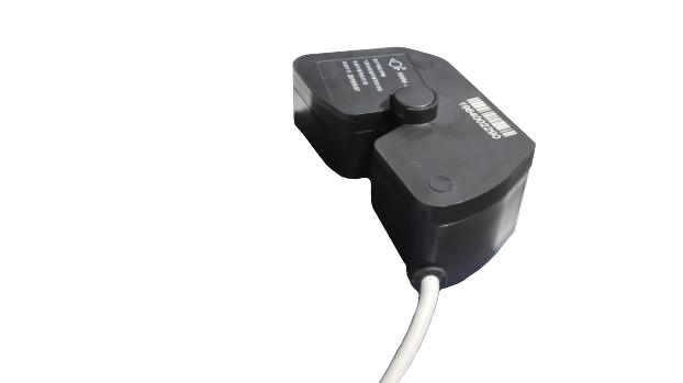
Negotiable
Non-magnetic Pulse Emission Device NWM-HRI
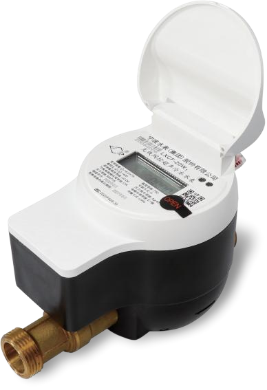
Negotiable
Fully Electronic Water Metering Solution
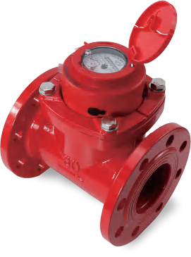
Negotiable
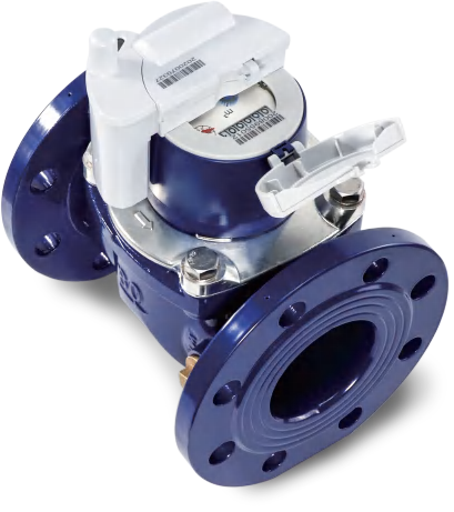
LXLC Horizontal Woltman Water Meter Series DN50~500
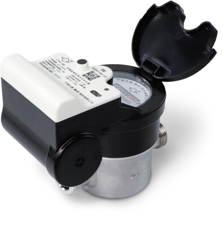
Negotiable
Direct Drinking Water Meter
Negotiable
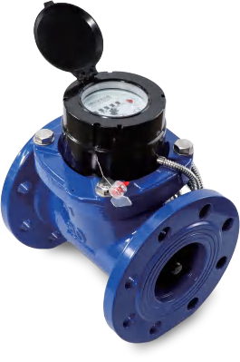
WPD Horizontal Woltman Water Meter Series DN40~300
Negotiable
WP5D Horizontal Woltman Water Meter Series DN50~500
Related Products
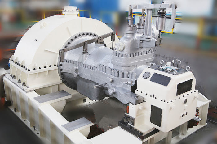
CITIC Heavy Industries Water Conservancy and Power Generation Equipment
Negotiable
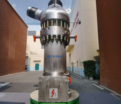
Coal-fired Boiler Startup Circulating Pump (Furnace Water Pump)
Negotiable
Process Pump-HHS
Negotiable
Industrial and Commercial Point-Type Gas Detector
Negotiable
DG Series Multistage Boiler Feed Water Pump
Negotiable
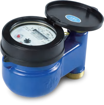
Economical Water Metering Solution
Negotiable