HF681N Series Multi-Drive VFD

EXW
$290.38-1,452.50 /Set
China
No.6 Ligongyuan Road, WUT National University Science Park, Donghu New Technology Development Zone, Wuhan
027-87923289
Online Contact
Favorite
Product Introduction

Product Overview:
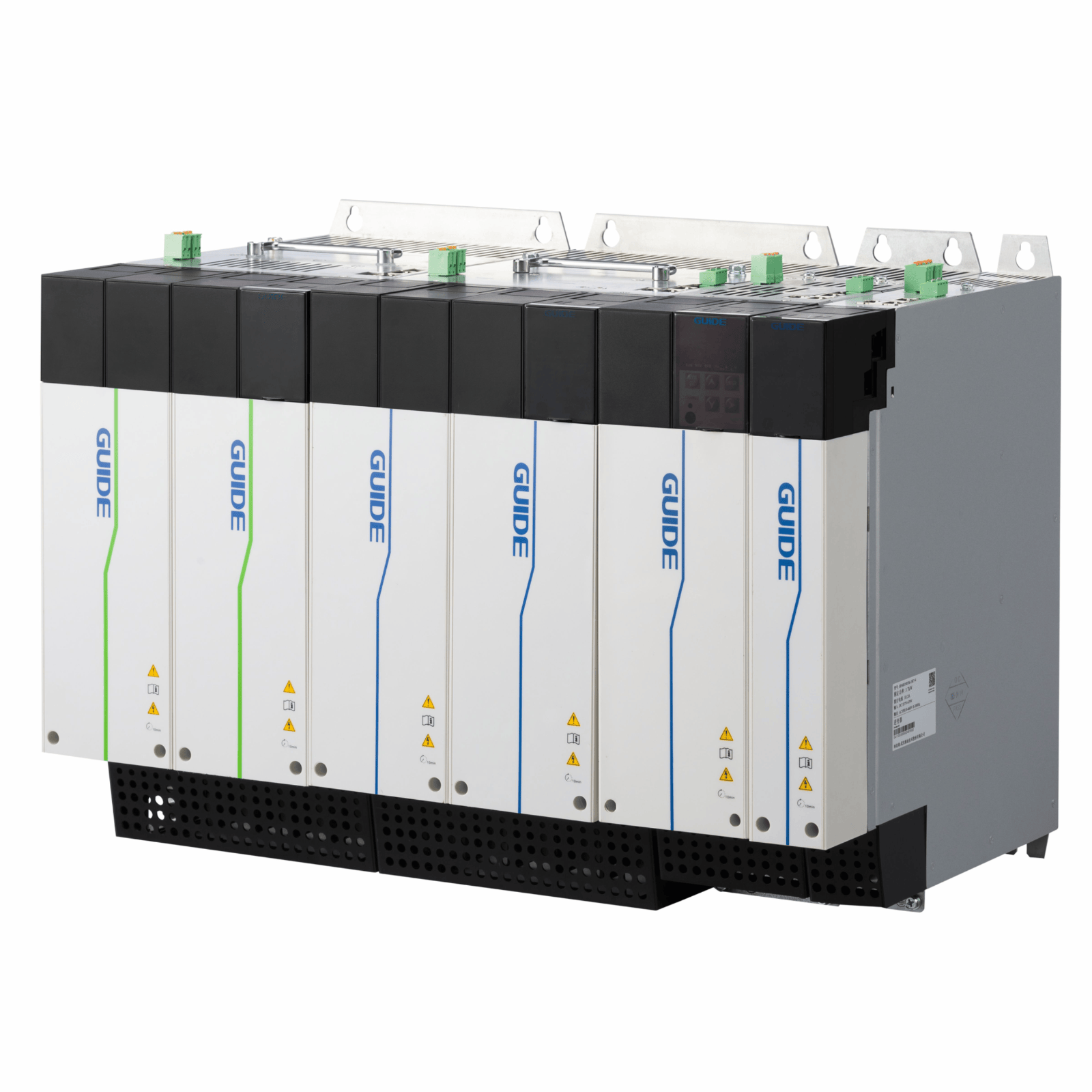
The HF681N series book-type multi-drive product includes rectifier units and inverter units. The product structure adopts an equal-height, equal-depth book-type modular design, featuring a side-by-side compact installation method with a small footprint. According to application requirements, one rectifier unit can be connected to multiple inverter units to form a common busbar drive system, enabling simultaneous control of multiple motors and achieving multi-point transmission. The product offers high reliability, excellent performance, high integration, good scalability, compact size, and ease of use.

☆ The product structure adopts an equal-height, equal-depth book-type modular design with a side-by-side compact installation method, resulting in higher cabinet utilization and a smaller footprint;
☆ The rectifier unit has a built-in braking unit. In multi-motor drive systems, a centralized braking design is used, requiring only one set of braking resistors to be configured in the rectifier unit;
☆ Inverter units with power ratings of 75kW and below have built-in DC fuses to prevent unit faults from propagating to the system, significantly improving system stability;
☆ The rectifier unit has a built-in DC reactor, which can effectively improve the power factor on the input side, enhance overall efficiency and thermal stability, and effectively eliminate the impact of high-order harmonics from the input side on the frequency converter;
☆ Each modular unit has a built-in mini rotary blade-type DC busbar, enabling quick connection and integrating components into the smallest possible space;
☆ The common busbar method allows energy to flow between inverter units. The electrical energy from inverter units in a generating state can be transferred via the DC busbar to inverter units in a motoring state, improving energy regeneration and utilization;
☆ The rectifier unit has a built-in process card with up to 43-way DI and 30-way DO channels, facilitating the implementation of various application processes;
☆ Supports multiple communication methods, facilitating data exchange between external controllers and the frequency converter system;
☆ Supports various expansion cards for convenient functional expansion.

Product Parameters

Project

Description

Input

Input voltage

Three-phase 380V ~ 480V

Rated frequency

50/60Hz

Allowable voltage fluctuation

-15% to + 10%

Allowable frequency fluctuation

The allowable range of frequency variation is fLN ± 2% (± 4% for independent power supply network).

Frequency change rate: ≤ 2% fLN/s.

Output

Output voltage range

0 ~ input voltage

Asymmetry of the output voltage

Under normal use conditions, in the entire output frequency adjustment range, the asymmetry of the output three-phase voltage should not exceed 1% under the condition of symmetrical load of each phase.

Output frequency range

0 to 300Hz

Control characteristics

Operation instruction mode

Panel control, terminal control, communication control.

Carrier frequency

1kHz ~ 10kHz, adjustable according to temperature and load characteristics.

Frequency resolution

Digital setting: 0.01Hz, analog setting: maximum frequency x0.1%

Control mode

Closed-loop vector control (VC), open-loop vector control (SVC), V/F control.

V/F control

Linear type, multi-point type, square type.

Torque control

There is PG torque control, no PG torque control.

Maximum speed

300Hz, depending on the electrical and mechanical characteristics of the motor.

Starting torque

0Hz/200%(VC and SVC), 0.8Hz/150%(V/F)

Speed range

1:500(SVC), 1:1000(VC)

Speed accuracy

± 0.02% rated speed (VC), ± 0.2% rated speed (SVC), ± 0.5% rated speed (V/F)

Overload capacity

The overload capacity is 150% of the rated output current, and the overload is allowed for 1 minute every 5 minutes.

Project

Description

Control characteristics

Torque compensation

Automatic torque compensation function.

Acceleration and deceleration mode

Line, user-defined multi-point curve.

Automatic voltage adjustment

When the grid fluctuates, it can automatically keep the output voltage constant.

DC braking mode

DC braking at startup and DC braking at shutdown.

Built-in process PID

It is convenient to realize the closed-loop control system of process quantity (pressure, temperature, flow, etc.).

Special features

User-programmable application-free function modules:

Logic function module, mathematical function module, timer module, PID module, etc;

Motion control:

Multi-curve acceleration/deceleration function, timer-controlled run/stop control, etc;

Crane function:

Power optimization, crane opening brake function.

Input/output

terminals

Input terminal

Rectifier unit configuration 43 D1 interface.

The inverter unit is configured with 8-way D1, 2-way AI and 2-way STO interfaces.

Shaft out terminal

The rectifier unit is configured with 30 DO interfaces.

The inverter unit is configured with 5 DO and 2 AO interfaces.

Man-machine interface

Operation panel LED

Can set the relevant parameters, can also display the output frequency, output voltage, output current and other parameters;

The operation status, fault status and parameter setting status shall have corresponding display contents: function, data and unit.

Protection function

Overcurrent protection, overvoltage protection, undervoltage protection, overheat protection, overload protection, etc.

Application scenarios

No direct sunlight, no dust and no corrosive environment.

Environment

Altitude

Less than 1000 meters, no derating required. For places with an altitude of more than 1000 meters, please reduce the rated voltage and rated output current by 1% for every 100 meters increase. When the altitude exceeds 3000 meters, it is necessary to consult the manufacturer for guidance.

Ambient temperature

-10 ℃ ~ +40 ℃, the ambient temperature exceeds 40 ℃, and derating is required. For every 1 ℃ increase in the ambient temperature, the derating rate is 1%. When the ambient temperature exceeds 50 ℃, consult the manufacturer for guidance. The ambient temperature is lower than -10 ℃, and additional auxiliary heating equipment is required.

Temperature

Less than 95% RH, no water condensation.

Storage

The storage temperature is -20 ℃ ~ +60 ℃. At the same time, due to the characteristics of the electrolytic capacitor, the storage time is more than half a year. The inverter needs to be powered on for 10-30 minutes every six months to charge the electrolytic capacitor.

Other

Efficiency

> 98%

Option card

The inverter unit control board is equipped with 2 slots, which can receive communication card, expansion IO card and PG card.

Other interfaces

External keyboard interface, CAN communication interface.

Protection level

IP20

Cooling mode

forced air cooling

Pollution level

2

Noise

≤ 80db