Gas Insulated Metal Composite Combined Electrical Apparatus (HGIS) ZHW13-126 (145) /3150-40

Negotiable
China
No.6 Xianghai Road, Xiamen Torch High-tech Zone (Xiang'an) Industrial Park
+86 592 3671600
Online Contact
Favorite
Product Introduction

The ZHW13-123 (145) HGIS electrical equipment is a new type of high-voltage power equipment. Based on the advantages of GIS combined electrical apparatus such as compactness, high reliability, and low operation and maintenance workload, it retains the on-site installation and docking busbars of GIS as conventional AIS layout, while cleverly solving the disadvantages of conventional AIS equipment such as large footprint, many connection links, and large maintenance workload. It is suitable for power plants, substations, stations and docks, large industrial and mining enterprises and other 145kV and below power transmission/distribution systems, especially for mountainous substations, urban substations and other projects with tight land use. It can be used for indoor, outdoor or rooftop installation.

Product Advantages

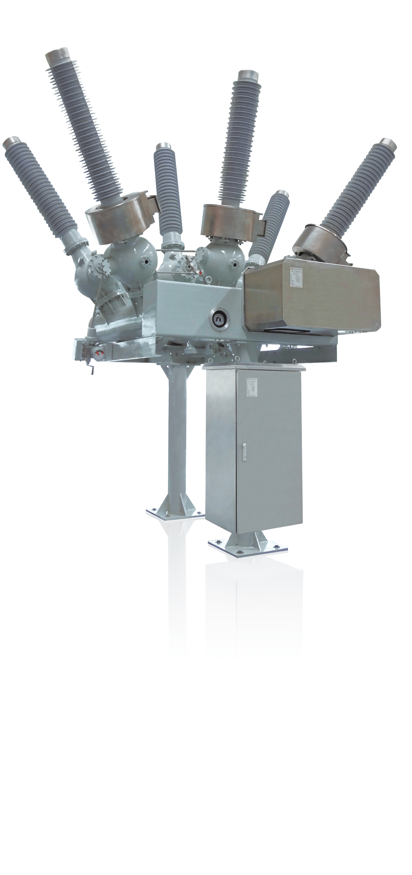
HGIS is a gas insulated metal composite combined electrical apparatus that concentrates circuit breakers, disconnecting/earthing combination switches, current transformers, and voltage transformers in one device.

This characteristic of HGIS equipment determines that, compared with GIS and AIS, it has the following advantages:

  • High operation reliability and small maintenance workload (basically maintenance-free for 25 years);
  • Can be directly installed outdoors, with extremely small civil engineering and electrical installation workload, and simple installation;
  • Small SF6 gas consumption (only 20% of GIS usage), green and environmentally friendly;
  • Low full life cycle cost;
  • Small size and light weight (silicone rubber bushings, aluminum tanks), high pollution resistance, hydrophobicity, and seismic resistance;
  • Short installation time and few power outages, very suitable for expansion or renovation projects of power plants and substations.


Product Parameters
Item Unit Parameter
Rated Voltage kV 123(145)
Rated Frequency Hz 50 
Rated Current A ≤3150
Rated Short-circuit Current kA 40 
Rated Peak Withstand Current kA 100 
Rated Power Frequency Withstand Voltage (1min)
Phase-to-phase and to ground Circuit breaker kV 230(275)
Disconnecting switch 230(275)
Across open contacts Circuit breaker 265(315)
Disconnecting switch 265(315)
Rated Lightning Impulse Withstand Voltage
Phase-to-phase and to ground Circuit breaker kV 550(650)
Disconnecting switch 550(650)
Across open contacts Circuit breaker 630(750)
Disconnecting switch 630(750)
Partial Discharge pC <5
SF6 Gas Room Pressure (20℃) MPa 0.6 
SF6 Gas Annual Leakage Rate   0.5%
Maintenance Interval Years 30 
Bushing Creepage Distance mm ≥4500

Bushing Terminal Load
Horizontal Static Load N 1250 
Transverse Static Load 750 
Vertical Static Load
1000


Circuit Breaker Type and Time Parameters
Rated Voltage kV 123(145)
Rated Frequency Hz 50 
Rated Current A ≤3150
Rated Operating Sequence   O-0.3s-CO-180s-CO
Opening Time ms 32±7
Closing Time ms 85±10
Reclosing Current-free Interval Time ms 300 
Rated Insulation Level
Rated Power Frequency Withstand Voltage (1min) To ground kV 230(275)
Across open contacts 265(315)
Rated Lightning Impulse Withstand Voltage To ground 550(650)
Across open contacts 630(750)
Short-circuit Breaking Capacity Parameters
Rated Short-circuit Breaking Current and First-pole-to-clear Factor kA 40/1.5
Transient Recovery Voltage Characteristics for Rated Outgoing Terminal Fault   Refer to IEC62271-100
Rated Thermal Stability Current (4s) kA 40 
Rated Dynamic Stability Current kA 100 
Rated Making Current kA 100 
Other Parameters
Number of Continuous Operations Allowed Without Maintenance Times 6000 
a. Number of Breaking Operations at Rated Short-circuit Current Times 20 
b. Number of Breaking Operations at Rated Current Times 6000 
Type of Operating Mechanism   Spring
Closing Power Supply of Operating Mechanism
a. Voltage V 220/110
b. Frequency   DC
C. Number of Closing Coils per Phase pcs
d. Steady-state Current of Each Closing Coil A 2.3/3.3
Opening Power Supply of Operating Mechanism
a. Voltage V 220/110
b. Frequency   DC
C. Number of Opening Coils per Phase pcs
d. Steady-state Current of Each Opening Coil A 2.7/5.7
SF6 Circuit Breaker Pressure Parameters (Absolute Pressure at 20℃)
Rated Air Pressure MPa 0.6 
Alarm Air Pressure MPa 0.55 
Lockout Air Pressure MPa 0.5 
SF6 Circuit Breaker Annual Leakage Rate   0.5%