
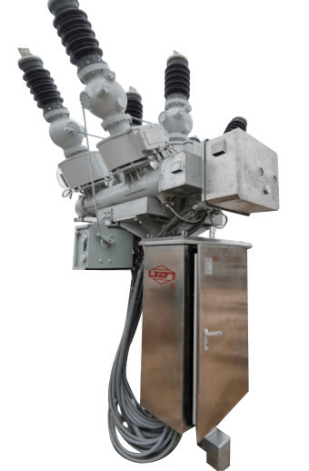
The ZHW12-40.5 gas insulated metal composite combined electrical apparatus (HGIS) is composed of several standard functional modules, such as circuit breakers, disconnecting/earthing switches, voltage transformers, current transformers, etc. These modules have the same interface forms and dimensions, and various modules can be combined to meet the design and layout requirements of various substations.
1/1

Gas Insulated Metal Composite Combined Electrical Apparatus (HGIS) ZHW12-40.5 / T200
Negotiable
China
No.6 Xianghai Road, Xiamen Torch High-tech Zone (Xiang'an) Industrial Park
+86 592 3671600
Product Introduction
Product Parameters
HGIS-40.5 Combined Electrical Apparatus Circuit Breaker Rated Parameters
| Item | Unit | Parameter | |
| Rated Voltage | kV | 40.5 | |
| Rated Power Frequency Withstand Voltage (1min dry/wet) |
To ground | 110 | |
| Across open contacts | 118 | ||
| Rated Lightning Impulse Withstand Voltage | To ground | 215 | |
| Across open contacts | 215 | ||
| Rated Frequency | Hz | 50 | |
| Rated Current | A | ≤2000 | |
| First-pole-to-clear Factor | 1.5 | ||
| Rated Short-circuit Breaking Current | kA | 31.5 | |
| Rated Short-circuit Making Current | 80 | ||
| Rated Short-time Withstand Current | 31.5 | ||
| Rated Peak Withstand Current | 80 | ||
| Rated Short-circuit Duration | S | 4 | |
| Rated Out-of-phase Breaking Current | kA | 7.9 | |
| Rated Operating Sequence | O-0.3s-CO-180s-CO | ||
| Opening Time | ms | 50±10 | |
| Closing Time | 90±20 | ||
| Make-break Time | ≤100 | ||
| Main Circuit Resistance | μΩ | ≤150 | |
| Rated SF6 Gas Pressure (20℃ gauge pressure) | MPa | 0.5 | |
| Alarm/Lockout Pressure (20℃ gauge pressure) | 0.45/0.4 | ||
| SF6 Gas Annual Leakage Rate | % | ≤0.5 | |
| Gas Moisture Content | ppm(v) | ≤150 | |
| Mechanical Life | Times | 6000 | |
Circuit Breaker Energy Storage Motor Technical Parameters
| Model | HDZ-16005A | HDZ-26005A | HDZ-36005A |
| Rated Voltage (V) | AC/DC 110 | AC/DC 220 | AC/DC 380 |
| Rated Power (W) | 660 | ||
| Normal Operating Voltage Range | 85%~110%Ue | ||
| Energy Storage Time at Rated Operating Voltage (s) | <8 | ||
Closing Coil Technical Parameters
| Rated Voltage (V) | DC 220 | DC 110 | |||
| Rated Current (A) | 2 | 3.3 | |||
| Rated Power Consumption (W) | 440 | 330 | |||
| Coil Resistance at 20℃ (Ω) | 110±10 | 33±1.6 | |||
| Operating Voltage Range | 80%~110%Ue | ||||
Opening Coil Technical Parameters
| Rated Voltage (V) | DC 220 | DC 110 | |||
| Rated Current (A) | 2 | 5.8 | |||
| Rated Power Consumption (W) | 440 | 638 | |||
| Coil Resistance at 20℃ (Ω) | 110±10 | 19±1 | |||
| Operating Voltage Range | 65%~120%Ue, no opening under continuous 3 operations below 30%Ue | ||||
Rated Parameters for Disconnecting Switch and Earthing Switch Section
| Item | Unit | Parameter | |||
| Disconnecting Switch | Earthing Switch | ||||
| Rated Voltage | kV | 40.5 | 40.5 | ||
| Rated Frequency | Hz | 50 | 50 | ||
| Rated Current | A | ≤2000 | |||
| Rated Insulation Level | |||||
| 1min Power Frequency Withstand Voltage (rms) | To ground | kV | 110 | ||
| Across open contacts | 118 | 118 | |||
| Lightning Impulse Withstand Voltage (peak) | To ground | 215 | |||
| Across open contacts | 215 | 215 | |||
| Control and Auxiliary Circuit 1min Power Frequency Withstand Voltage (rms) | kV | 2 | 2 | ||
| Rated Short-time Withstand Current | kA | 31.5 | 31.5 | ||
| Rated Short-circuit Duration | S | 4 | 4 | ||
| Rated Peak Withstand Current | kA | 80 | 80 | ||
| Mechanical Life | Operations | 3000 | 3000 | ||
| Pole-to-pole Opening/Closing Asynchrony (not greater than) | ms | 150/300 | 150/300 | ||
Isolation/Earthing Switch Motor Operating Mechanism Main Parameters
Front Three-position Disconnecting Switch
| Item | Unit | Parameter | |||||||||
| Rated Voltage | V | DC 220 | |||||||||
| Rated Output Power | W | 140 | |||||||||
| Rated Current | A | 1.4 | |||||||||
| Starting Current | A | 5 | |||||||||
| Mechanism Output Shaft Angle | ° | -45 to +45 | |||||||||
| Moving Contact Travel Angle | ° | 45±1 | |||||||||
| Opening/Closing Time | S | 2±1 |
Rear Three-position Disconnecting Switch
| Item | Unit | Parameter | |||||||||
| Rated Voltage | V | DC 220 | |||||||||
| Rated Output Power | W | 140 | |||||||||
| Rated Current | A | 1.4 | |||||||||
| Starting Current | A | 5 | |||||||||
| Mechanism Output Shaft Angle | ° | -90 to +90 | |||||||||
| Moving Contact Travel Angle | ° | 90±1 | |||||||||
| Opening/Closing Time | S | 5.5±1 |
| Arrester Model | Arrester Rated Voltage | System Rated Voltage | Arrester Continuous Operating Voltage | DC Reference Voltage | Continuous Current Resistive Component | 2ms Square Wave Current | Steep Wave Impulse Current Residual Voltage | Lightning Impulse Current Residual Voltage | Switching Impulse Current Residual Voltage | Power Frequency Reference Voltage | |
| kV (rms) | kV ≥ | mA (peak) ≤ | A (peak) | kV (peak) ≤ | kV (rms) ≥ | ||||||
| CY5W-51/134 | 51 | 35 | 23.4 | 75 | 0.15 | 400 | 154 | 134 | 114 | 51 | |
| CY5W-54/142 | 54 | 35 | 23.4 | 80 | 0.15 | 400 | 163 | 142 | 121 | 54 | |
Auxiliary Switch: 10 normally open contacts and 10 normally closed contacts in total; the contacts can carry a continuous current of no less than 10A.
Travel Switch: Can provide 1-4 pairs of normally open and normally closed contacts; the contacts can carry a continuous current of no less than 5A.
Terminal Block: The terminal block can carry a continuous current of no less than 10A.
Other products from this supplier

Negotiable
Gas Insulated Metal-enclosed Switchgear (GIS) ZF48-126 (145) /T3150-40
Negotiable
Gas Insulated Metal Composite Combined Electrical Apparatus (HGIS) ZHW13-126 (145) /3150-40
Negotiable
Gas Insulated Metal-enclosed Switchgear (GIS) ZF-252/T4000-50
Negotiable
MNS Low Voltage Switchgear
Negotiable
SGC1 Armored Air-insulated Metal-enclosed Switchgear
Negotiable
VX1-40.5kV Vacuum Circuit Breaker with Modular Spring Operating Mechanism
Negotiable
ZW32-12/630-20 Outdoor High Voltage AC Vacuum Circuit Breaker
Negotiable
SGC1- 12C / 40.5C Series Gas Insulated Switchgear (C-GIS)
Negotiable
H-40.5/0.4~1.14kV New Energy Power Generation Dedicated High Voltage/Low Voltage Prefabricated Substation
Related Products
Weichai Land-based Diesel Genset WPG110F1
Negotiable
Post-type AC Pollution-resistant Disc Suspension Porcelain Insulator (Triple Umbrella Type)
Negotiable
Intelligent SF₆ Ring Main Unit
Negotiable
ABS Lithium Bromide Unit
Negotiable
Combined honeycomb ceramic
Negotiable
MCU Output Busbar Assembly
Negotiable
Smart Photovoltaic Prefabricated Substation
Negotiable
10kV Oil-immersed Station Service Transformer
Negotiable
G.652.D Wavelength-extended Non-dispersion Shifted Single-mode Optical Fiber
Negotiable
Intelligent Cluster Charging Unit
40000-200000 /Set
Green Wind Power
Negotiable
Single-Phase Automatic Voltage Regulator(AVR)
Negotiable