

I. Product Overview and Definition
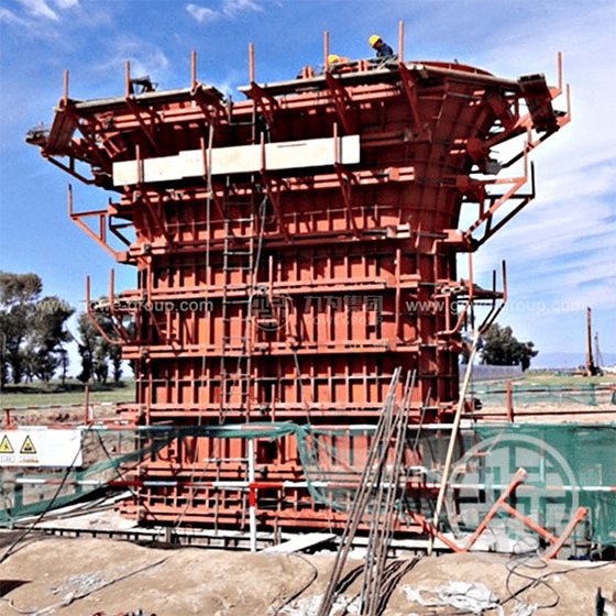
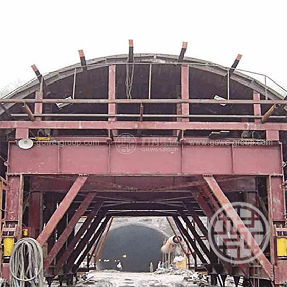
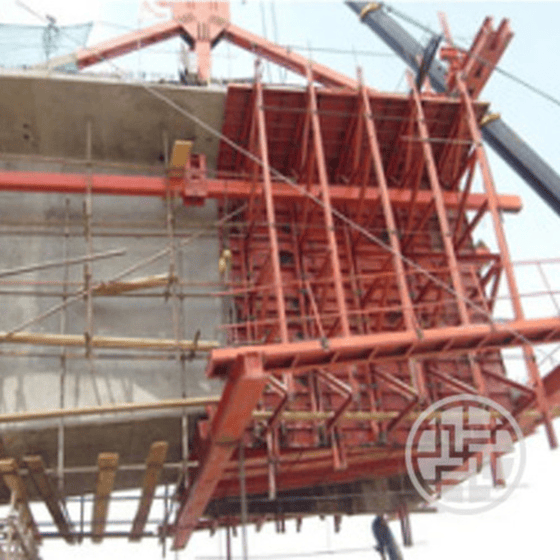
The form traveler is the core load-bearing structure and mobile working platform for long-span continuous beams, continuous rigid-frame bridges, and cable-stayed bridges when thecantilever cast-in-place construction method is adopted .
The form traveler is primarily anchored and suspended from the already cast beam segments, providing an elevated working platform for rebar tying, prestressing duct installation, concrete placement, and tensioning operations of the next segment (standard segment length typically 3~5m) . Once a segment is completed and prestressing is applied, the form traveler can move forward along the rails on top of the beam under its own power and be re-anchored, cyclically proceeding to the next segment until the entire cantilever placement of the bridge is finished .
II. System Classification of Form Travelers
Form travelers can be classified into the following categories based on structural configuration, movement method, and anti-overturning load characteristics :
-
Classification by Structural Configuration:
Triangular form traveler: Simple structure, clear load transfer path, high rigidity, and minimal deformation; it is one of the most widely used mainstream types .
Diamond / modified diamond form traveler: Low center of gravity, excellent stability, no longitudinal cross-interference above the beam top, and a spacious working area .
Front-support (stay-cable type) form traveler: Suitable for cable-stayed bridges or heavy-duty super-large cross-section beam segments, significantly reducing the bending moment of the form traveler itself .
Others: bowstring type, cable-stayed type, steel-section type, truss type, hybrid type, etc. .
-
Classification by Load-Bearing / Load-Carrying Arrangement:
- Deck-type form traveler: The main load-bearing truss is located above the beam top.
- Under-slung form traveler: The main load-bearing truss is located below the beam, offering high space utilization and being particularly suitable for conditions with restricted clearance (e.g., overhead high-voltage lines or existing lines) .
2. Classification by Movement Method: Sliding type, rolling type, and combined type .
3.Classification by Balancing / Anti-Overturning Method: Anchored type (using rear anchoring to resist overturning), counterweight type, and semi-counterweight anchored type .
III. Four Core System Components of the Form Traveler
Each subsystem of the form traveler is self-contained and works in coordination with the others :
-
Main Truss Load-Bearing System (Main Truss)
-
Composed of the main truss, cross beams, columns, and diagonal tension rods, it bears the self-weight of the concrete, formwork weight, and construction loads, and is typically precision-fabricated from high-strength structural steel .
-
-
Formwork System (Formwork System)
-
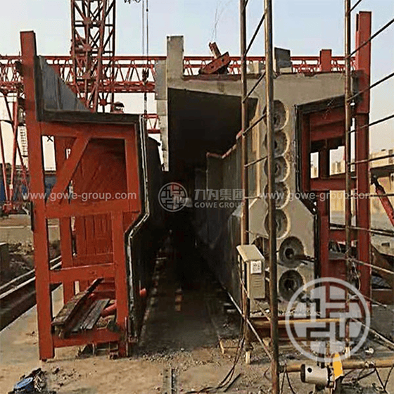
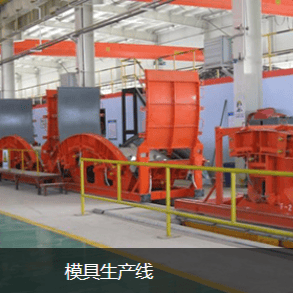
Includes theexternal form, internal form, bottom form platform (bottom cage), and end form . The external form and bottom form move forward together with the form traveler as a whole; the internal form is typically designed as a hydraulically or mechanically stripped integral sliding carriage system .
-
-
Suspension and Anchoring System
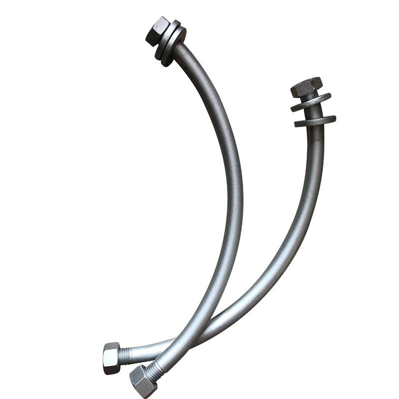
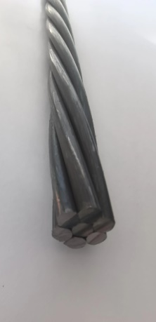
- Suspension system: Uses high-strength precision-rolled threaded steel rods to suspend the bottom form platform and external form from the main truss .
- Rear anchoring system: Uses precision-rolled threaded steel pre-embedded in the cast beam top to firmly secure the tail of the main truss, eliminating the traditional bulky rear counterweight .
4. Travel and Thrust System
-
-
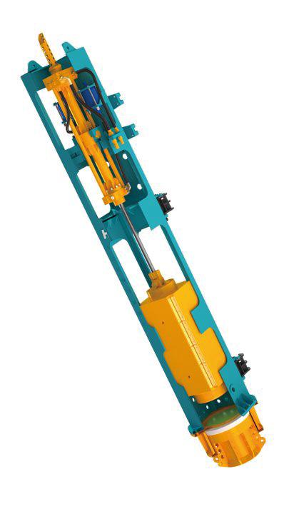
Includes dedicated rails laid on the beam top, anti-derailing rollers/thrust devices, and hydraulic jacks (or traction equipment), enabling smooth and safe forward movement of the form traveler .
-
IV. Key Technical Parameters
| Parameter Item | Technical Specification and Requirements | Remarks / Basis of Specification |
| Standard Casting Segment Length | 3.0 m – 5.0 m / segment |
Common control range for segment construction |
| Formwork Steel Plate Thickness | ≥ 5 mm |
Ensures rigidity and flatness, preventing deformation and grout leakage |
| Anti-Overturning Safety Factor | ≥ 2.0 | Safety indicator during form traveler movement and concrete placement |
| Concrete Curing Time | Not less than 7 days |
Ensures the beam body strength reaches the tensioning requirements |
| Rebar Cover Spacers | High-strength mortar spacers, density ≥ 4 pcs/m² |
Appropriately densified at critical load-bearing and weak areas |
| Formwork Assembly Requirements | In-factory / on-site 100% trial assembly verification |
Strictly inspect rigidity, flatness, joint tightness, and structural dimensions |