

Principle and Structure:
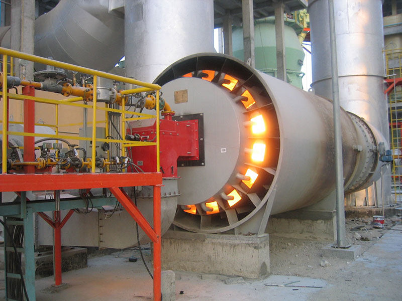
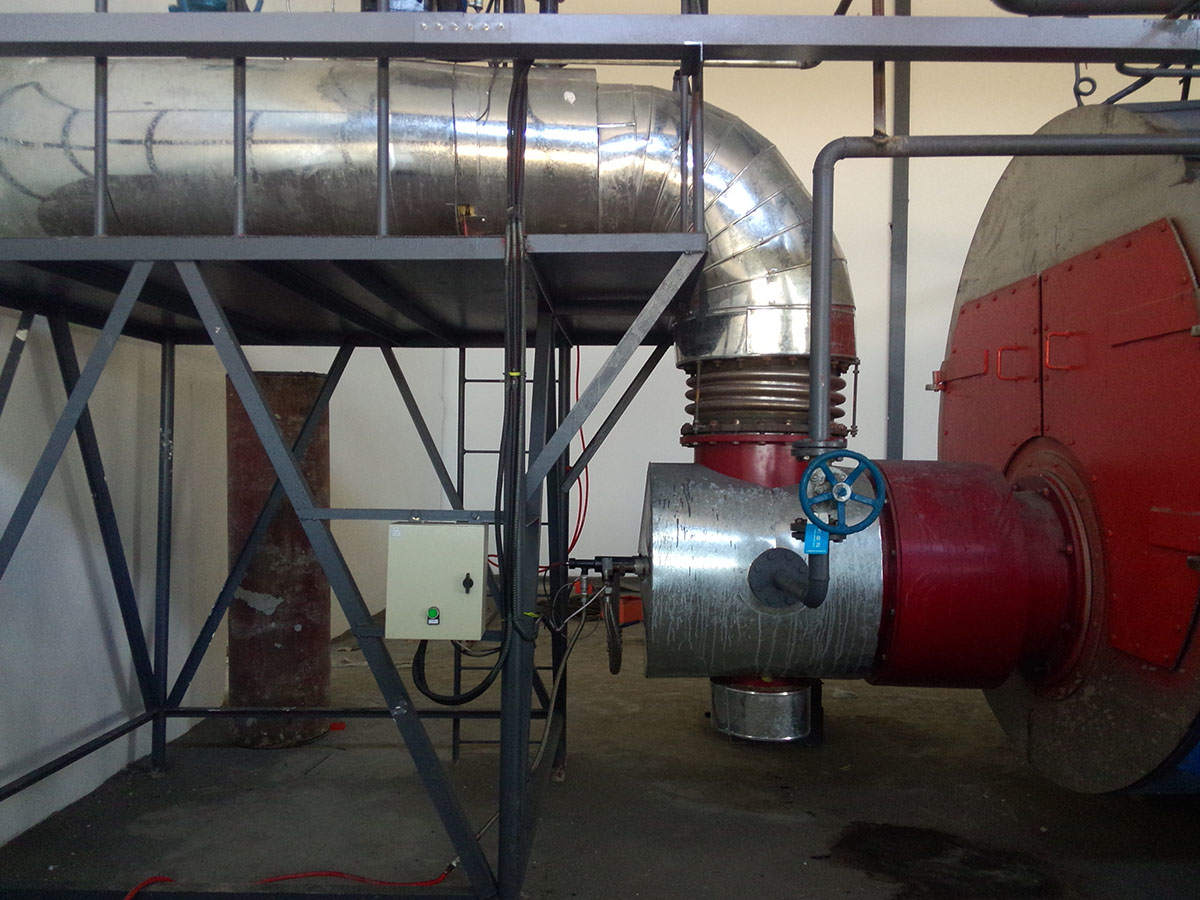
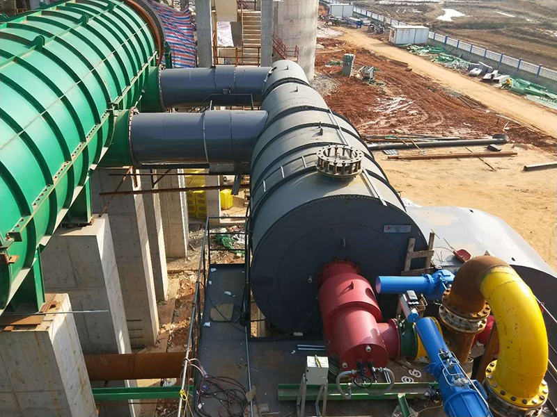
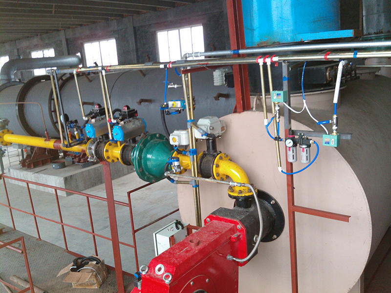
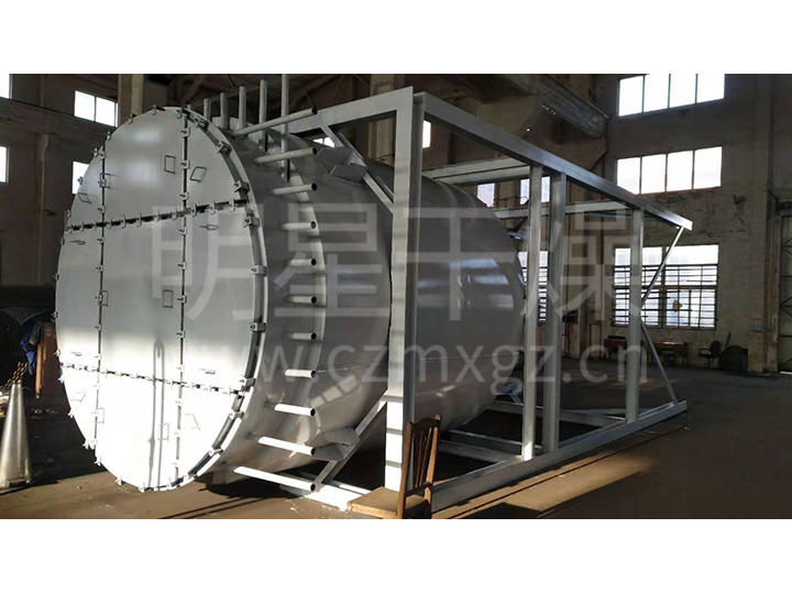
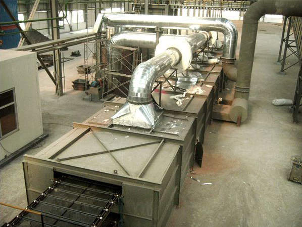
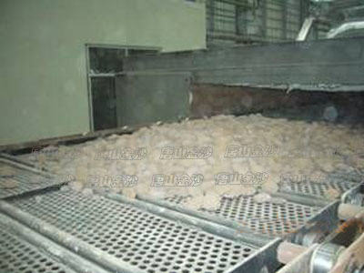
The flip-plate dryer is a drying equipment based on the bidirectional conveying principle. It is a continuous automatic dryer with wide application and strong adaptability. It features a small footprint and high drying efficiency. Moist material flows from the tail of the dryer through the feed hopper onto the upper-layer grid plates of the dryer. The feed hopper buffers and distributes the material. The material runs smoothly on the grid plates to the head of the dryer, flows down to the lower layer through the flip-plate mechanism, and is then conveyed back to the tail. This cycle repeats, and the material is gradually dried under hot air baking and discharged from the tail. The hot air supply can be configured according to user conditions, such as an independent hot air furnace or hot flue gas.
Product Performance Features:
1. The guide rails adopt a light-rail composite structure, optimally designed according to material characteristics and distribution features, ensuring straightness and strength. The sprocket running resistance is low, and the flip-plate mechanism coordinated by the guide rails ensures smooth flipping of the plates.
2. The sprockets are equipped with automatic tensioning devices, ensuring stable operation of the chain plates. Combined with well-matched guide rails, this effectively solves problems such as chain derailment, jamming, and deviation.
3. The flip plates are made of heat-resistant steel punched into a mesh pattern, featuring high strength, resistance to deformation, and good air permeability. Chain rollers are connected on both sides of the flip plates, ensuring the rollers on both sides are coaxial and facilitating easy disassembly and installation.
4. The chain plates are driven by electromagnetic speed regulation or variable-frequency speed regulation according to working conditions, allowing adjustment of operating speed as needed to control drying time.
5. Fire prevention devices are installed. Temperature measurement devices with digital displays are installed at the kiln head, middle, and tail, making it easy to monitor and control the temperature inside the kiln. A flue gate is provided at the flue air inlet; in the event of mechanical failure, the heat source can be immediately isolated to prevent fire.
6. Based on the initial moisture content and characteristics of the material, top air supply or interlayer air distribution is adopted. The hot air is evenly distributed and effectively prevents the material from cracking or bursting due to rapid heating, thereby improving material quality and reducing breakage rate.
7. Negative-pressure induced draft or positive-pressure forced draft is reasonably selected according to conditions such as material moisture content and hot air temperature.
8. Special cleaning equipment is installed at the lower part of the machine to discharge dust particles, thereby reducing usage intensity and equipment failures.
Notes:
1. This equipment is non-standard equipment, and its external dimensions are related to the following factors:
(1) Hot air temperature and humidity, as well as the method of hot air generation
(2) Process interface considerations — whether material enters and exits at one end, or enters at one end and exits at the other
(3) Whether a powder cleaning device is required
(4) According to the user's site conditions, the height, length, and width of the equipment can all be varied
(5) The structural form of the kiln body
2. The power parameters of the equipment are related to material characteristics, working conditions, and layout configuration.
3. The scheme for this equipment can only be determined after technical consultation.