ROOMTOP Leaky Cable Solution
Negotiable
China
Zhongtian Village, Hekou Town, Rudong County, Jiangsu Province
86-0513-83599738
Online Contact
Favorite
Product Introduction
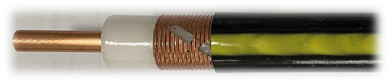
  1. ROOMTOP 1.0 features a copper outer conductor, offering excellent transmission performance, suitable for scenarios with high signal quality requirements.

ROOMTOP 2.0 uses an aluminum outer conductor, providing good performance at a lower cost, ideal for large-area coverage scenarios with relatively lower signal quality demands.

  1. Application Scope: Leaky coaxial cables are suitable for wireless communication scenarios below 6GHz, particularly for strip-shaped indoor areas such as office buildings, dormitories, corridors, and open spaces like underground parking lots. As a carrier for wireless signal transmission and radiation, they achieve uniform signal coverage, meeting the signal demands of 4G/5G mobile communications, emergency communications, and other scenarios.
  2. Product Advantages:

Uniform Signal Coverage: Signals radiate evenly along the cable length, addressing signal dead zones in narrow and elongated areas, with coverage stability superior to conventional antennas.

Convenient Installation and Maintenance: The integrated cable structure eliminates the need for additional antenna brackets, allowing direct installation along walls, cable trays, etc. Troubleshooting is straightforward, improving maintenance efficiency.

Wide Bandwidth Compatibility: Supports full-band signal transmission below 6GHz, compatible with 4G, 5G, and future next-generation mobile communication technologies, reducing the need for frequent cable replacements and lowering long-term usage costs.

Product Parameters

ROOMTOP 1.0 (copper leaky cable)

Structure

Project

Parameters

Type

Radiation type

Nominal dimensions

7/8"

Insulation material

Physical foaming polyethylene

outer conductor material

Longitudinal Corrugated Copper Foil

Sheath material

Polyolefin

Outer diameter and color of sheath

25.8±0.3mm/black

Mechanical properties

Project

Nominal value

Tensile strength

2000N

Minimum static bending radius

250mm (Single bend)

Recommended hanger spacing

<2m

Installation temperature

-20 ~ +60 ℃

Working temperature

-40 ~ +80 ℃

Storage temperature

-10 ~ +50 ℃

Electrical performance

Project

Parameters

Radiation angle

≥ 170°

Cut-off band

1350-1550MHz,2170-2300,

2400-2515,2800-3000MHz,3300-3400

Polarization mode

vertical polarization

Standing wave ratio

<1.2

Characteristic impedance

50±2 Ω

DC resistance of inner conductor

3.0Ω/km

DC resistance of outer conductor

3.5Ω/km

Working frequency band

800~960, 1700~2200, 2300~3600MHz

Insulation strength

10000V( DC,1 min.)

Minimum insulation resistance

8000MΩ·km

Sheath spark test voltage

8000V(AC)

Attenuation

Frequency (MHz)

Attenuation (dB/100m)

Coupling loss (0°)

MHz

dB/100m, 20℃

95%, 2m, dB

800

3.92

81

900

4.15

82

1800

6.81

76

1900

7.22

73

2000

7.66

75

2100

7.88

76

2300

8.47

76

2400

8.75

75

2600

9.40

75

2620

9.45

74

2700

9.66

75

3300

12.30

67

3400

13.26

70

3500

13.91

71

3600

14.55

73

3700

15.10

71

3800

15.90

73

ROOMTOP 2.0 (aluminum leaky cable)

Structure

Project

Outer diameter (mm)

Materials

Inner conductor

9.0±0.3

Aluminum tube

Insulation

/

Polyethylene foam

Aluminum outer conductor

23.2±0.3

Longitudinal corrugated aluminum foil

Sheath

25.8±0.3

Low-smoke halogen-free flame retardant polyolefin

Mechanical properties

Project

Single

Nominal value

Minimum static bending radius

mm

280 (single)

Maximum tensile strength

N

1500

Installation temperature

-25 ~ +60 ℃

Working temperature

-20 ~ +85 ℃

Storage temperature

-55 ~ +85 ℃

Electrical Performance

Project

Parameters

Characteristic impedance

50±2 Ω

Relative transmission speed

88%

Minimum insulation resistance

10000MΩ·km

Working frequency band

800~960, 1700~2200, 2300~3600MHz

Cut-off band

1350-1550MHz, 2170-2300,

2400-2515, 2800-3000MHz, 3300-3400

Insulation strength

10000V( DC,1 min.)

Sheath spark test voltage

8000V(AC)

Standing wave ratio

1.30

Attenuation

Band (MHz)

Attenuation (dB/100m)

Coupling loss (/95%,2m)

800

4.2

87

900

4.9

83

1800

7.0

71

2100

7.9

69

2400

8.9

70

2600

9.6

70

2700

9.9

68

3400

14.1

66

3500

14.9

63

3600

15.9

64