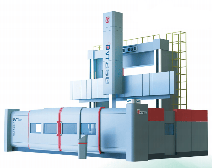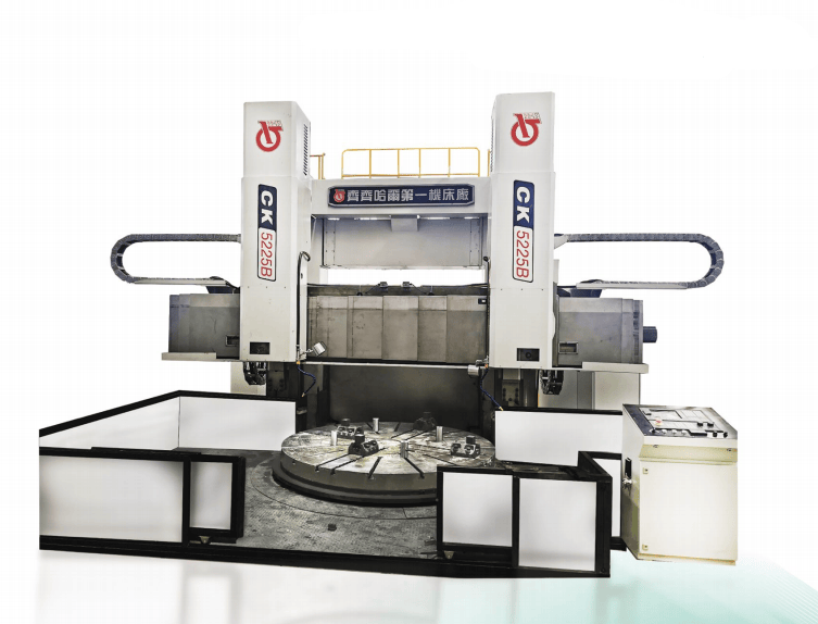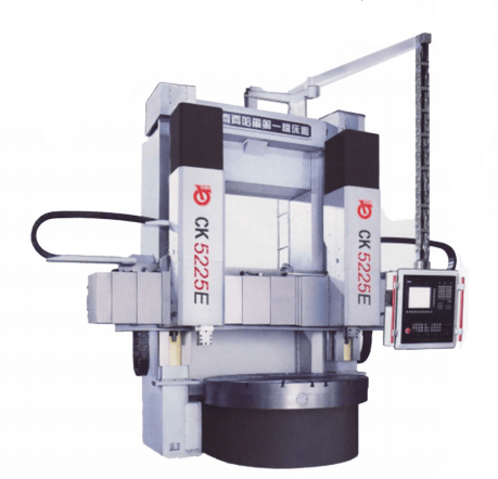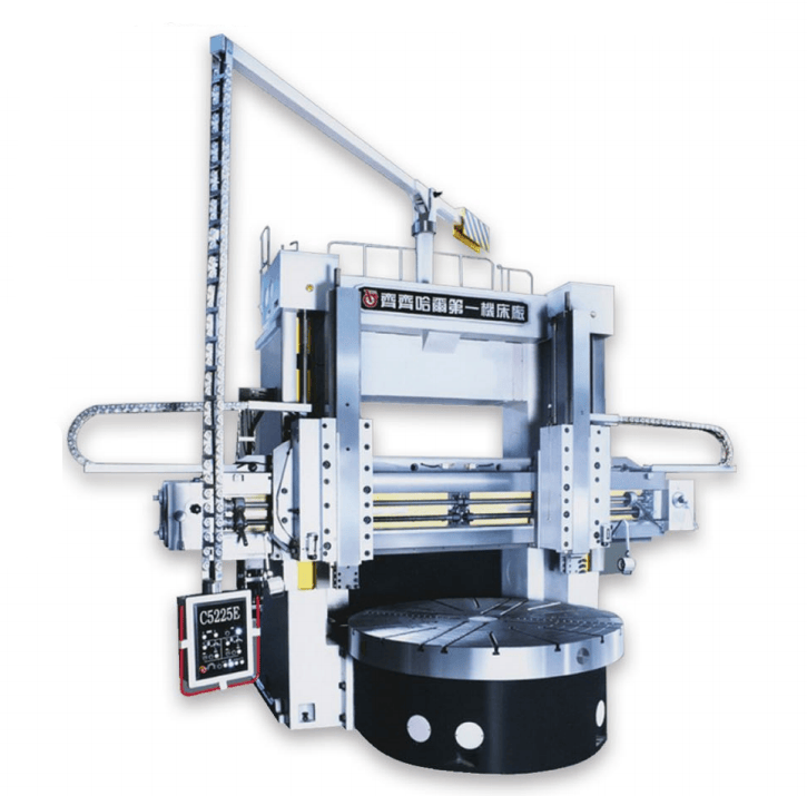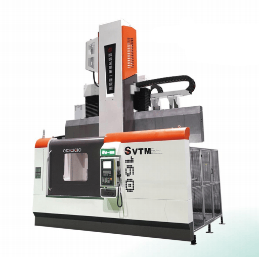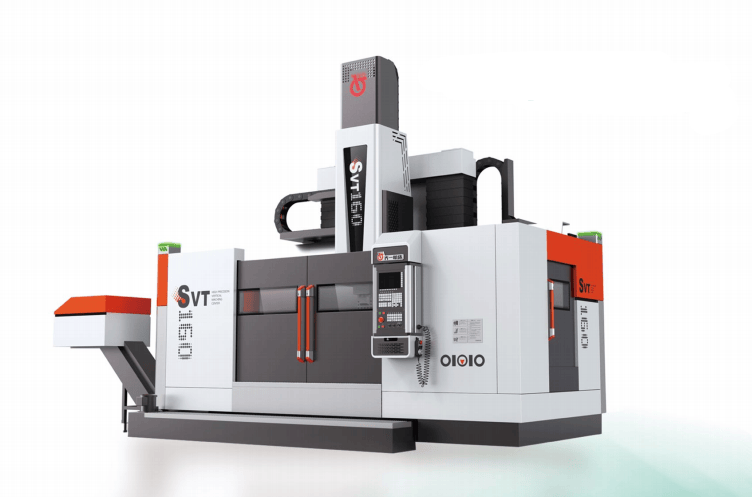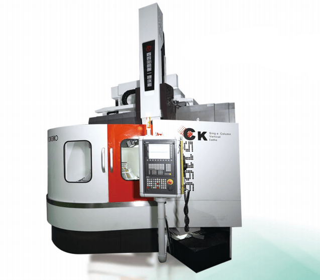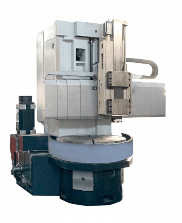
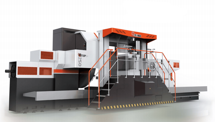


The product is mainly used for machining rotary parts such as shafts and discs, and is an indispensable machining equipment for large motors, generator main shafts, and various types of rotors.
The HT II P series is an integral three-guideway CNC heavy-duty horizontal lathe with a machining diameter of φ1600-φ2500mm and a load capacity of 32~80 tons. The bed guideways are wide and highly rigid, making it more suitable for machining with large cutting forces.
The HT II series is an integral four-guideway CNC heavy-duty horizontal lathe with a machining diameter of φ1250-φ2000mm and a load capacity of 20~40 tons. The bed guideway structure is superior, making it more suitable for compound and ultra-high-precision machining.
The bed guideways of the HT II P series feature an integral three-guideway structure. The middle guideway is a common guideway with large space and good chip evacuation. It is manufactured by induction hardening and grinding, offering good thermal stability, cutting stability, high load capacity, and long service life. The tool post and bed are fully protected by stainless steel covers.
The bed guideways of the HT II series feature an integral four-guideway structure. The middle guideway is a guiding guideway with superior guideway protection and chip evacuation. It is manufactured by induction hardening and grinding, offering good thermal stability, cutting stability, and long service life. The tool post and bed are fully protected by stainless steel covers.
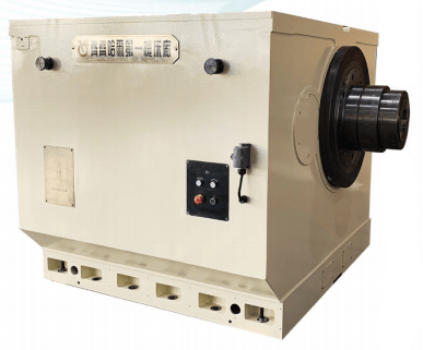
Designed through finite element analysis, it adopts a double-wall anti-vibration box structure. The spindle uses high-precision rolling bearings and a short spindle structure. Through advanced detection methods and mature assembly processes, high precision and low noise of the headstock are achieved.
The headstock base and the headstock are connected by a thermally symmetrical mechanism to prevent thermal drift.
The tailstock is of an integral box-type structure with high strength and large load capacity; the high-precision double-row cylindrical roller bearings support the quill, providing large load capacity and high precision.
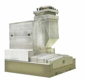
Through finite element analysis and modular design, the tool post features high cutting rigidity, high transmission rigidity, fast response speed, and high motion and positioning accuracy. A variety of tool post configurations are available, including left-right tool row structures or electric tool turret structures.
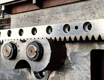
The transverse (X-axis) movement of the tool post adopts a servo motor-reducer-ball screw structure, and the longitudinal (Z-axis) movement adopts a servo motor-reducer-ball screw or double gear-rack structure. The structure is simple and reliable, with few intermediate links, high precision, and easy maintenance.
Reliable mechanical force-amplifying jaws are provided on the faceplate. The faceplate is fastened to the spindle with screws and an interference-fit conical surface, ensuring more reliable connection.
The X and Z axes of the tool post are driven by Siemens AC motors and equipped with a high-precision position feedback system — Heidenhain linear encoders.
An encoder is provided at the rear end of the spindle to enable thread machining and constant surface speed cutting.