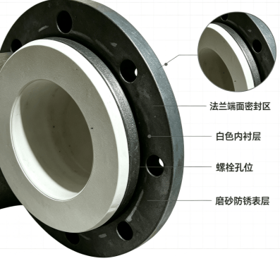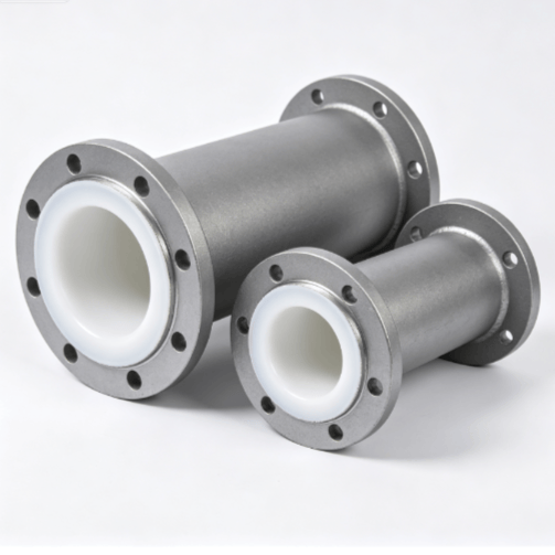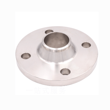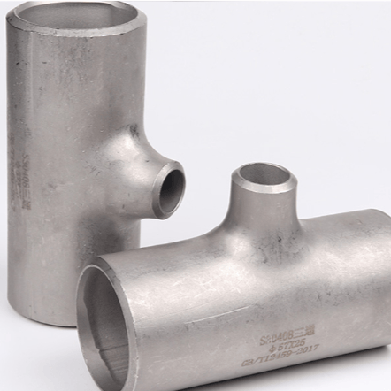

Chemical Prefabrication

Negotiable
China
No. 77, Dongliu Village, Yanshan Town, Yanshan County
19831733300
Online Contact
Favorite

Product Introduction

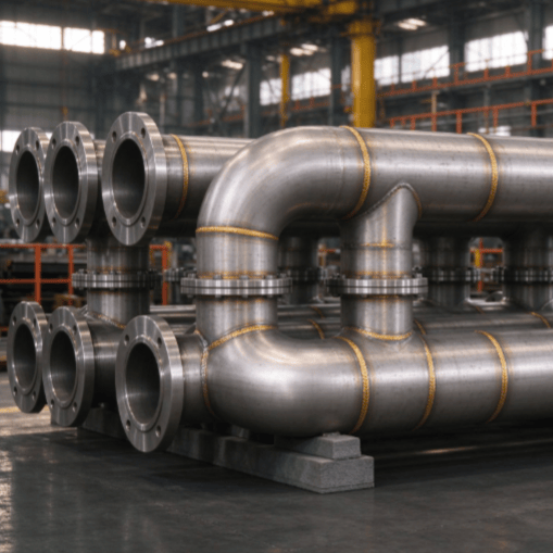
Chemical prefabricated welded components are assemblies or modules manufactured in a factory workshop according to construction drawings, through processes such as cutting and forming, beveling, fit-up and welding, inspection and pressure testing of pipes, profiles, and steel plates, then transported to the site for integral hoisting and assembly. Compared with on-site piece-by-piece construction, factory prefabrication can shorten on-site construction time by 30%~50%, provide more stable weld quality, and is less affected by weather. It is widely used in petroleum, chemical, natural gas, coal chemical, nuclear power, municipal pipeline networks, and other facilities.

II. Main Product Categories

Table

Category Typical Form Application Scenario
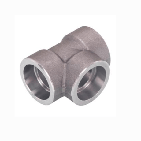
Pipe Spool Prefabricated Components Straight pipe + elbow + tee + flange welded pipe rack Process piping, utility piping
Steel Structure Welded Modules Pipe rack supports, equipment frames, operating platforms, equipment bases Plant pipe racks, steel structure frames
Pressure Vessel Components Cylinder shells, heads, nozzle flanges, manholes, reinforcing rings Reactors, heat exchangers, storage tanks, towers
Non-standard Equipment Shells Silos, chimneys, flues, equipment enclosures Environmental protection, storage and transportation, auxiliary systems

III. Commonly Used Materials

  • Carbon Steel: Q235B, Q355B (Q345B), 20# seamless pipe, Q345R vessel plate
  • Stainless Steel: 304/304L, 316/316L, 321, 310S
  • Alloy Steel: 15CrMo, 12Cr1MoV, P91/P22 (high-temperature and high-pressure service)
  • Clad Plate: Stainless steel + carbon steel explosion-bonded clad plate (corrosion resistance + pressure-bearing economy)

IV. Manufacturing Process and Technical Parameters

Table

Item Content
Welding Method GTAW argon arc welding (root pass), SMAW manual arc welding, FCAW flux-cored gas-shielded welding, SAW submerged arc automatic welding
Beveling Machining / flame cutting, V-type, double V-type or U-type bevel, root face and angle per WPS
Welder Qualification Certified welders, working per NB/T 47014 Welding Procedure Qualification (PQR) + Welding Procedure Specification (WPS)
Non-destructive Testing RT radiographic, UT ultrasonic, MT magnetic particle, PT penetrant; pressure-containing welds generally Grade II acceptance per design requirements
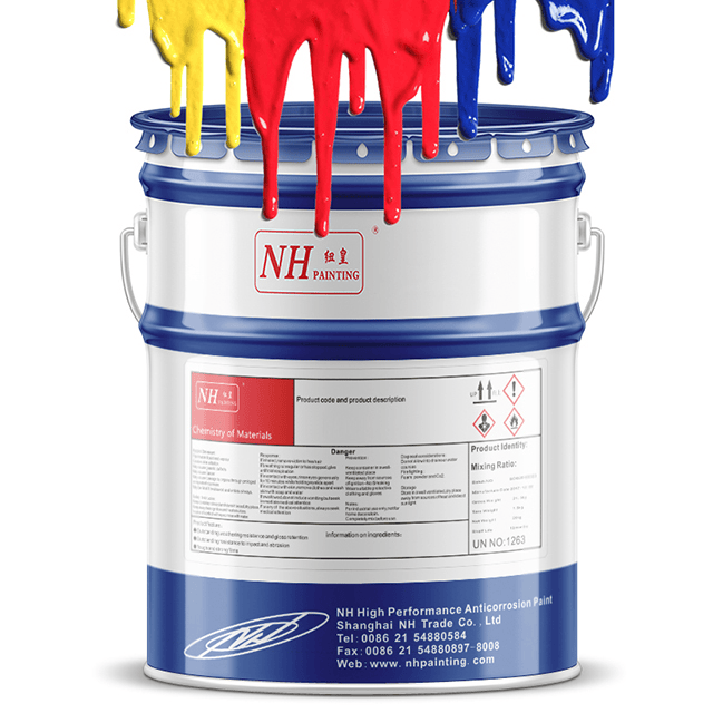
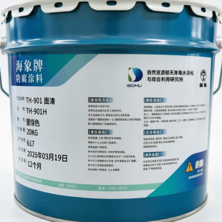
Surface Treatment Sandblasting to Sa2.5 grade, anti-rust primer + topcoat; stainless steel parts pickled and passivated
Size Range Piping DN15 ~ DN1200; plate thickness 3 ~ 80 mm; single module up to tens of tons
Design Parameters Design pressure vacuum ~ 42 MPa; design temperature -196 ℃ ~ 600 ℃ (depending on material grade)
Flange Standards GB/T 9119, HG/T 20592, SH/T 3406, ANSI B16.5, JIS B2220
Applicable Standards GB 50235 "Code for Construction of Industrial Metallic Piping", GB 50236 "Code for Construction of Field Equipment, Industrial Pipe Welding Engineering", GB 150 "Pressure Vessels", NB/T 47014

V. Quality Control Key Points

  1. Material Traceability: Base materials and welding consumables all have material certificates, with transferred identification numbers traceable throughout the entire process.
  2. Pre-weld Preheating / Interpass Temperature: Alloy steel and thick plates preheated per WPS, interpass temperature controlled.
  3. Weld Inspection: 100% visual inspection + proportional RT/UT, stainless steel additionally subjected to PT dye penetrant testing.
  4. Pressure Testing: Pressure-containing components subjected to hydrostatic / pneumatic testing before delivery per design (per drawing requirements).
  5. Document Delivery: As-built documentation includes material certificates, welding records, heat treatment records, NDT reports, pressure test records, as-built drawings.

Product Parameters

I. Pipe Spool Prefabricated Components

Parameter Specification / Range
Nominal Diameter DN15 ~ DN1200 (1/2" ~ 48")
Pipe Outer Diameter φ21.3 ~ φ1220 mm
Wall Thickness Grade Sch10S ~ Sch160, wall thickness 2.11 ~ 60 mm
Common Pipe Standards GB/T 8163 (seamless steel pipe), GB/T 14976 (stainless steel seamless pipe), GB/T 12459 (butt-welding pipe fittings)
Common Materials 20#, Q355B, 304/304L, 316/316L, 15CrMo, 12Cr1MoV, A106B, A312 TP304/TP316L
Connection Standards HG/T 20592, GB/T 9119, SH/T 3406, ANSI B16.5, JIS B2220
Flange Pressure Rating PN6 ~ PN160 (Class 150 ~ Class 2500)
Bevel Type V-type 60°±2.5°, root face 1~2 mm; double V or U-type for thick walls
Welding Method GTAW argon arc welding root pass + SMAW manual arc welding / FCAW flux-cored fill and cap; SAW automatic welding for straight pipe girth welds
Weld Inspection 100% visual; butt welds RT / UT per design proportion; stainless steel parts additionally PT penetrant testing; acceptance level typically Grade II
Pressure Testing Hydrostatic test at 1.5 times design pressure; pneumatic test at 1.15 times design pressure (per drawing)
Applicable Standards GB 50235 "Code for Construction of Industrial Metallic Piping", GB 50236 "Code for Construction of Field Equipment, Industrial Pipe Welding Engineering", NB/T 47014

II. Steel Structure Welded Components (Pipe Rack / Frame / Equipment Base)

Table

Parameter Specification / Range
Section Steel Specifications H-beam HW/HM/HN 100×100 ~ 900×300; I-beam I10 ~ I63; channel steel [10 ~ [40; angle steel L50×5 ~ L200×24
Steel Plate Thickness 6 ~ 80 mm
Common Materials Q235B, Q355B (Q345B), Q355B-Z15 (thick plate resistant to lamellar tearing), Q235C (low temperature)
Welding Method GMAW gas-shielded welding / FCAW flux-cored semi-automatic; SAW submerged arc automatic welding for long welds
Fillet Weld Leg hf Per design, typically 6 ~ 12 mm; tolerance 0 ~ +3 mm, strictly not below design value
Weld Quality Grade Grade I, II, III (GB 50205); Grade I 100% UT, Grade II 20% UT sampling
Fabrication Tolerance Component length ±3 mm; overall bending deflection ≤ L/1000 and ≤ 10 mm; end flatness ≤ 2 mm
Surface Treatment Abrasive blasting to Sa2.5 grade (GB/T 8923.1)
Coating System Epoxy zinc-rich primer 2×40 μm + epoxy mica iron intermediate coat 60 μm + polyurethane topcoat 2×40 μm, total dry film thickness ≥ 200 μm; fluorocarbon topcoat may be used for outdoor weather-resistant type
Applicable Standards GB 50661 "Code for Welding of Steel Structures", GB 50205 "Standard for Acceptance of Construction Quality of Steel Structures"

III. Pressure Vessel / Storage Tank Welded Components

Table

Parameter Specification / Range
Cylinder Inner Diameter DN400 ~ DN4000 (can be enlarged per design)
Wall Thickness 6 ~ 80 mm (rolled); forged nozzle up to 150 mm
Common Materials Q345R, Q370R, 20R, S30408 (304), S31603 (316L), S32168 (321), Q345R+S30408 explosion-bonded clad plate
Design Pressure Vacuum (-0.1 MPa) ~ 42 MPa
Design Temperature -196 ℃ (cryogenic) ~ 600 ℃ (heat-resistant steel)
Welding Method GTAW root pass + SMAW / FCAW fill; SAW submerged arc automatic welding for cylinder longitudinal and girth welds
Post-weld Heat Treatment Carbon steel ≥ 32 mm, alloy steel ≥ 14 mm stress relief heat treatment, 600 ~ 650 ℃ holding time 2~3 min/mm per plate thickness
Non-destructive Testing Category A (longitudinal welds, girth welds) 100% RT or UT, Grade II acceptance; Category B (nozzle fillet welds) 20%~100% MT/PT per design
Pressure Testing Hydrostatic test at 1.25 times the ratio of allowable stress at design temperature; pneumatic test at 1.15 times
Applicable Standards GB 150.1~4 "Pressure Vessels", TSG 21 "Supervision Regulation on Safety Technology for Stationary Pressure Vessels", NB/T 47014 "Welding Procedure Qualification for Pressure Equipment", NB/T 47015 "Welding Specification for Pressure Vessels"

IV. General Quality Assurance

Table

Item Requirements
Material Traceability Complete certificates for base materials / welding consumables, material transfer numbers traceable throughout to finished product identification
Personnel Qualification Welders hold special equipment operator certificates, NDT personnel hold Grade II or above qualifications
Process Documents Product Welding Procedure Qualification PQR + Welding Procedure Specification WPS covering all material / thickness / position combinations
Delivery Documents Material quality certificates, welding records, heat treatment curves, NDT reports, pressure test reports, as-built drawings, product quality certificates