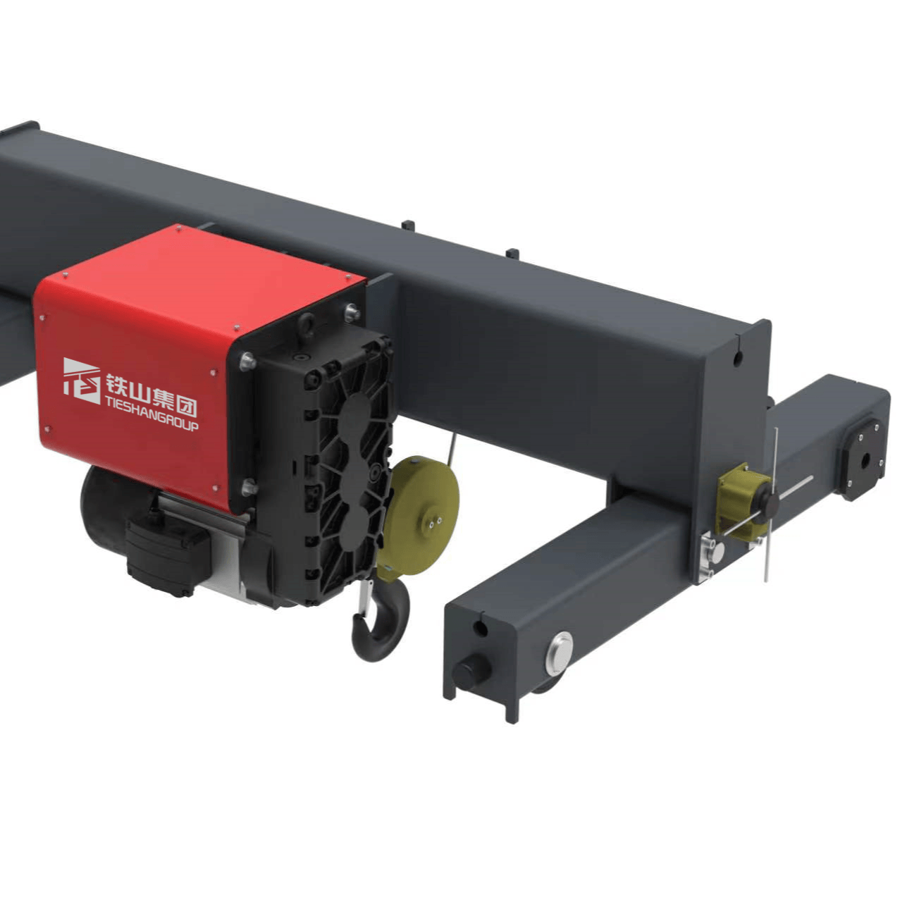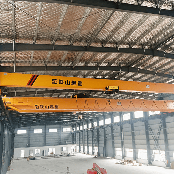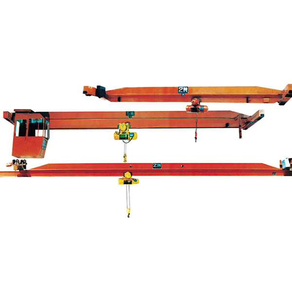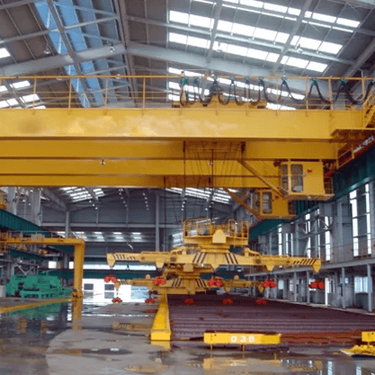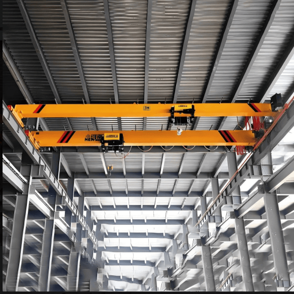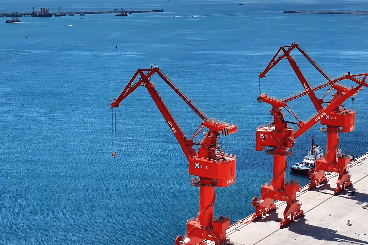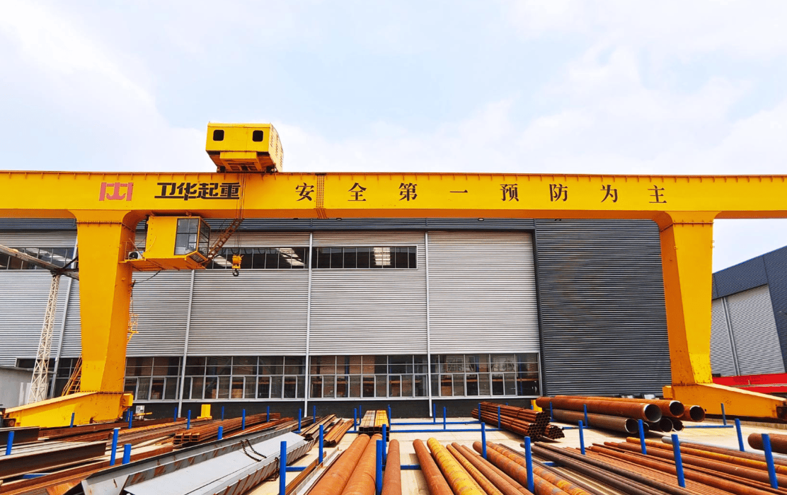
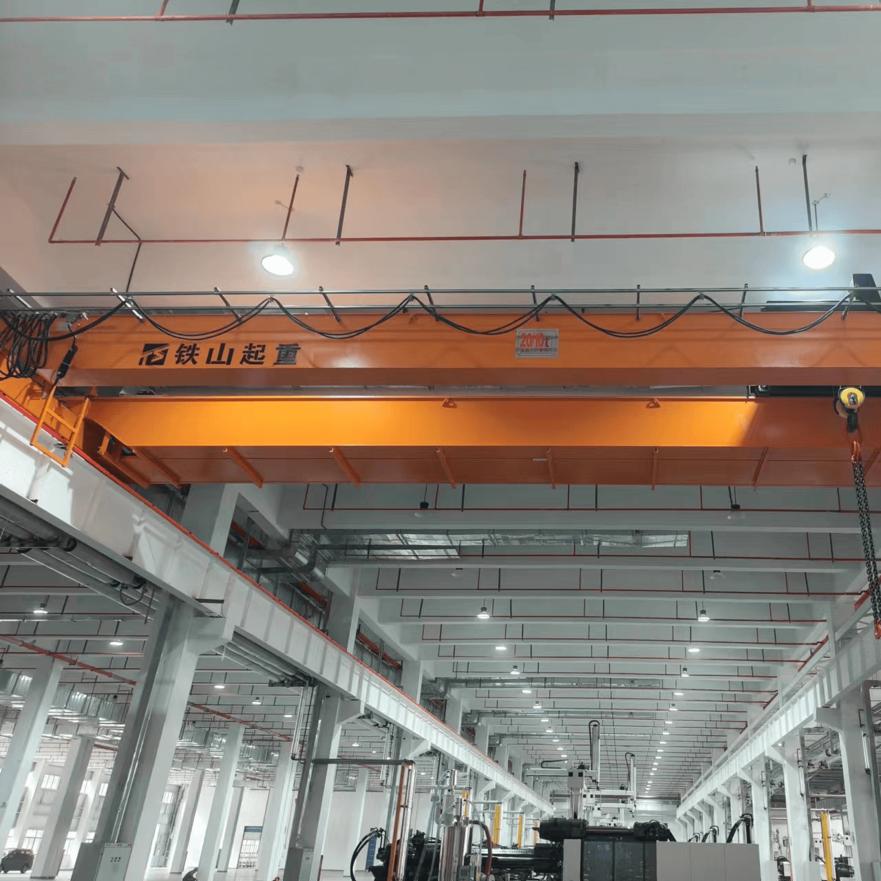
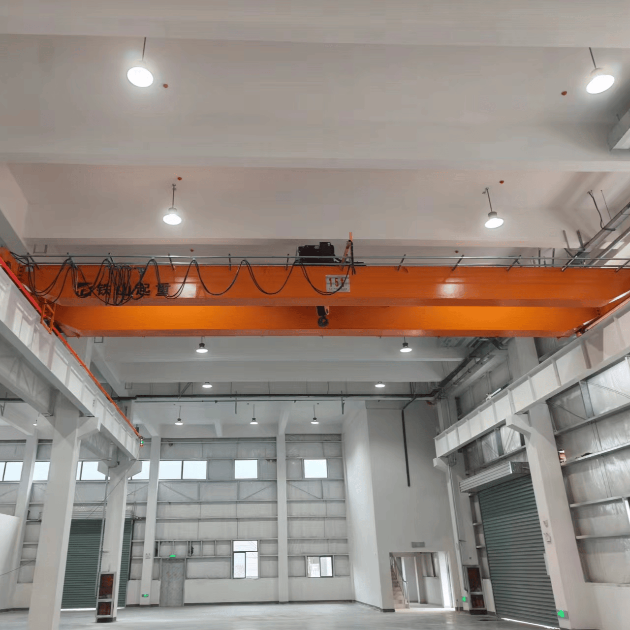
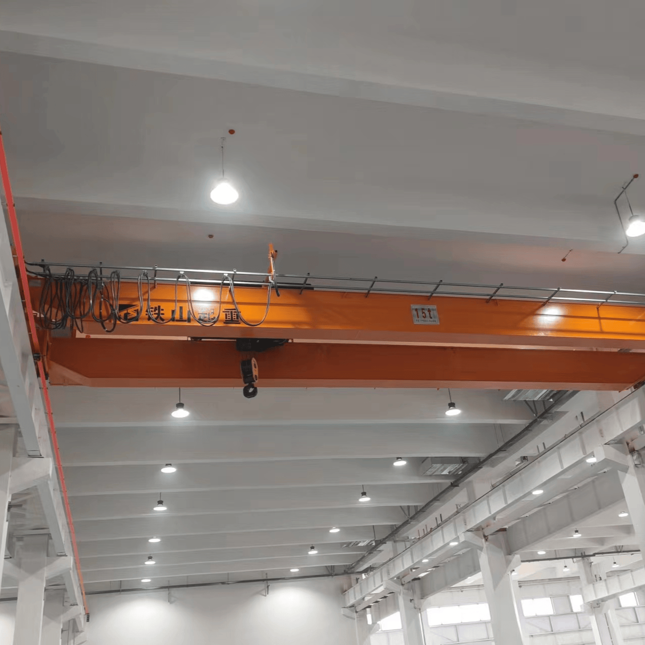
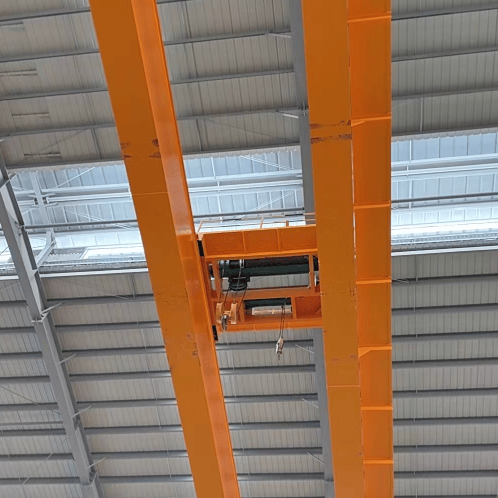
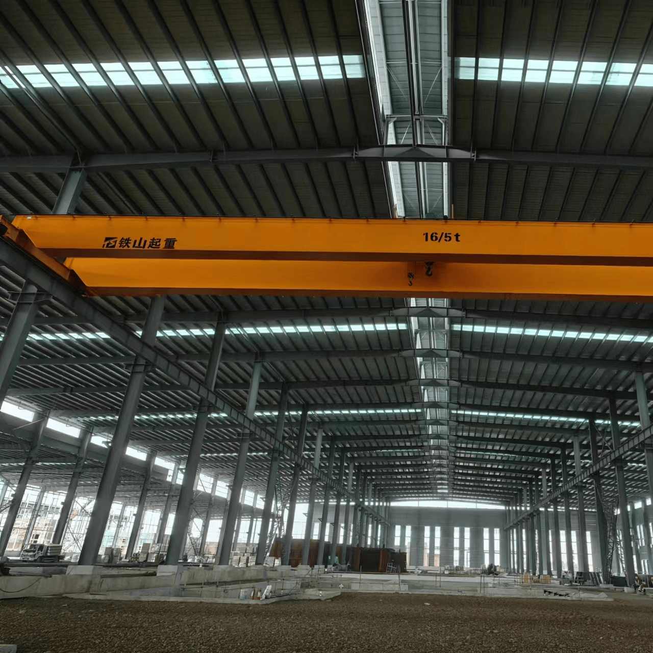


The double girder bridge crane, commonly known as the double girder overhead crane or double girder traveling crane, is manufactured in accordance with the national standard GB/T14405‑2011 "General Purpose Bridge Cranes". It is primarily used for lifting and transporting heavy loads in indoor workshops and factories. The metal structure consists of two box-type main girders plus end carriages, with the trolley traveling on rails atop the two main girders, enabling three-dimensional operations: hoisting, trolley transverse movement, and crane longitudinal movement.
Three Major Components of the Complete Crane
- Metal Structure: Bridge frame (dual main girders, end carriages, walkway platforms and railings), trolley frame;
- Mechanical Mechanisms: Hoisting mechanism, trolley travel mechanism, crane travel mechanism;
- Electrical System: Motors, brakes, control cabinets, conductor rails, safety protection devices.
Main Models
- QD Type: Traditional winch-trolley double girder bridge crane (most common in China), lifting capacity 5‑500t;
- LH Type: Electric hoist double girder bridge crane, for light to medium duty, 5‑32t, lightweight and low headroom;
- QE Type: Double-trolley double girder bridge crane, two trolleys can operate independently or in synchronization;
- European Type: Lightweight variable-frequency double girder crane, designed to FEM European standards, with lower overall deadweight and reduced wheel loads.
Control Methods
Cabin operation, pendant pushbutton control, wireless remote control, with variable frequency speed regulation available.
Working Environment
Standard: ‑20℃ to +40℃, altitude ≤1000m, indoor use; explosion-proof and high-temperature metallurgical versions require custom design.
Key Advantages
High rigidity, excellent torsional resistance, and strong load-bearing capacity, suitable for heavy-duty and frequent operation; can be equipped with various lifting attachments such as grabs, electromagnetic chucks, and C-hooks.
Application Industries
Machining, equipment assembly, steel structures, mold workshops, heavy industry, power plants, mining, and warehousing.