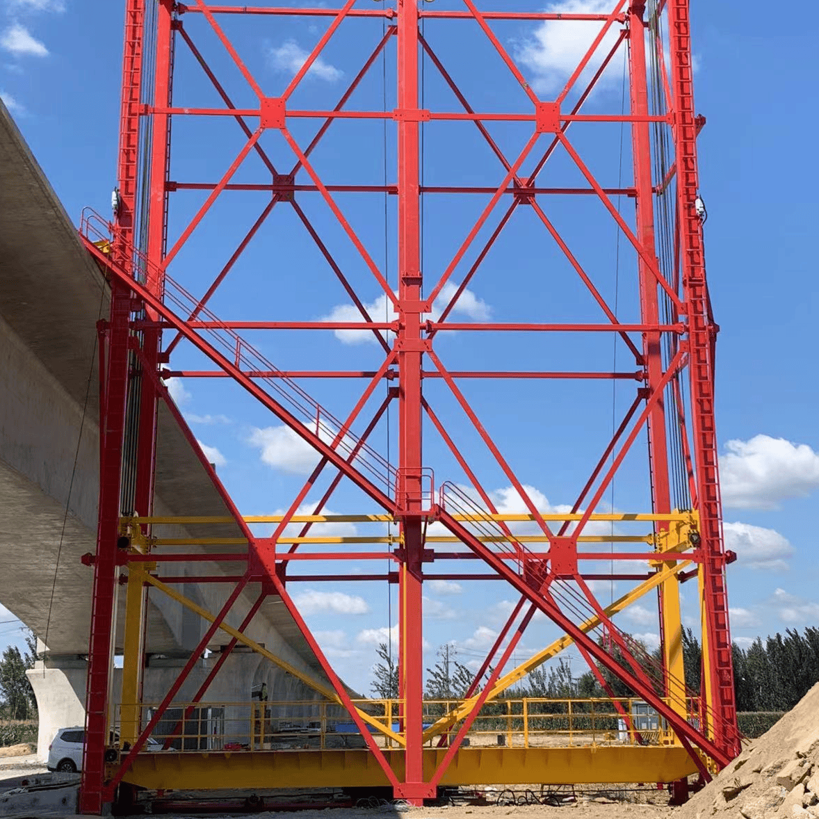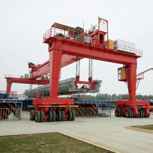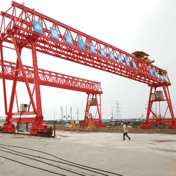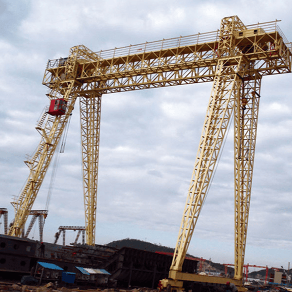
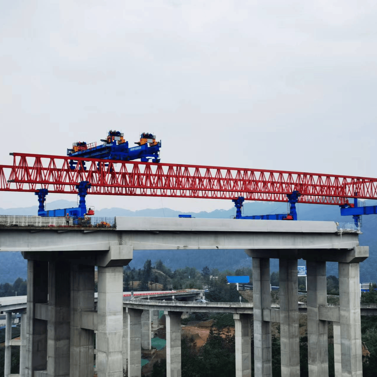


The self-balanced bridge erection machine is an upgrade of the traditional walking-type bridge erection machine. Relying on the main girder truss structure, multiple sets of hydraulic outriggers, and PLC center-of-gravity attitude monitoring, it achieves self-propelled hole crossing without counterweights. It is mainly used for erecting precast T-beams, small box girders, and U-shaped girders on highways and intercity elevated roads. It can erect straight bridges, skew bridges, curved bridges, and bridges with large longitudinal and transverse slopes, and supports bidirectional beam erection without turning the entire machine around.
Main Components of the Machine
- Metal Structure: Twin-plate truss main girders (Q355B high-strength steel, assembled with pins and bolts), front outrigger, middle outrigger, rear outrigger, front auxiliary outrigger (core component of self-balancing), and upper crossbeam;
- Hoisting Mechanism: Two overhead crane trolleys responsible for beam lifting, longitudinal movement, and transverse movement of the entire machine with the beam, enabling one-step positioning of edge beams;
- Walking Travel System: Outriggers alternately lift – step – lower in a walking motion for hole crossing; no long-distance longitudinal track needs to be laid on the bridge deck;
- Hydraulic System: Each outrigger is independently hydraulically lifted and leveled, with a maximum working pressure of 31.5 MPa;
- Electrical and Safety Monitoring System: PLC + variable frequency drive, with inclination, pressure, and displacement sensors for real-time monitoring of the machine's center of gravity, tilt, and outrigger reaction forces, equipped with a full set of limit switches, anemometer, emergency stop, and torque safety monitoring system.
Core Advantages
- ✅Truly self-balanced hole crossing: No counterweights or beam transport vehicle tail weighting required. The beam transport vehicle can return directly to the beam yard after delivering the beam, improving efficiency;
- ✅Strong adaptability to complex working conditions: Suitable for longitudinal slope ≤5%, transverse slope ≤5%, skew bridges up to 45°, and small curve radii of 260 m and above;
- ✅Bidirectional beam erection without turning the entire machine around; can pass through tunnels and erect beams directly at tunnel portals;
- ✅Edge beams are positioned in one step via transverse movement of the entire machine, eliminating secondary handling;
- ✅Fast disassembly, assembly, and site transfer; modular bolted and pinned connections require fewer transport vehicles and less labor;
- ✅Walking-type forward movement means the middle outrigger does not travel long distances on the already-erected beam surface, making it more friendly to the bridge deck.
Scope of Application
Expressways, municipal elevated roads, and intercity rail transit; erection of precast small box girders, T-beams, and U-beams; complex construction sites such as road crossings, river crossings, and tunnel portals.
⚠️ Distinction: 900-ton high-speed railway bridge erection machines are mostly of the integrated transport-and-erection type and do not fall into this category of self-balanced walking bridge erection machines.