
From Process Measurement to Emergency Shutdown: The Role of Automation Instruments in Functional Safety
en.Wedoany.com Reported - In refining, chemicals, natural-gas processing, pharmaceuticals and other process industries, Automation Instruments do more than maintain production and product quality. They may also help prevent overpressure, excessive temperature, leakage, fire and runaway reactions. When basic process control cannot stop a hazardous condition, a safety instrumented system must detect the event and move the process toward a safe state.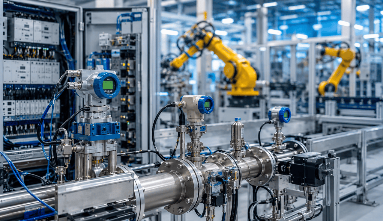
A safety instrumented system normally includes sensors, a logic solver and final elements. Sensors identify the hazardous condition. The logic solver determines whether the trip criteria have been met. Final elements such as shutdown valves, relays, motor controls or emergency isolation devices perform the protective action. Failure in any part of this chain can reduce the reliability of the safety function.
IEC 61511 provides requirements for the specification, design, installation, operation and maintenance of safety instrumented systems in the process sector. Its objective is to establish confidence that the system can achieve or maintain a safe state when required. The standard uses a lifecycle approach rather than treating safety as a one-time equipment-purchase decision.
The lifecycle begins with hazard and risk analysis. The organization must identify hazardous scenarios, existing protection layers and the additional risk reduction required. Safety functions can then be specified, designed and verified. Installation, commissioning, operation, proof testing, modification and eventual decommissioning are also included in the management process.
A safety integrity level is not simply a quality label attached to one transmitter or valve. It represents the required risk-reduction performance of a defined safety instrumented function. Achieving that performance depends on the complete architecture, including sensor voting, logic, final elements, diagnostics, proof-test interval, repair time and common-cause failures.
This distinction prevents a common procurement error. Purchasing a transmitter marketed for a high safety integrity application does not automatically create a safety function with the same capability. The transmitter must be used within an appropriate system design, and its failure data, diagnostics and application limits must be incorporated into the calculation and verification.
Independence is an important engineering principle. If the basic control system and the safety system share one sensor, power supply, communication path or process connection, a common failure may disable both control and protection. Whether sharing is acceptable must be determined through risk analysis and architectural requirements. Critical functions often need suitable separation in measurement, logic or final actuation.
Redundancy should also be evaluated carefully. Two pressure transmitters connected to the same impulse line may both lose the process signal if that line becomes blocked. Three temperature sensors installed in the same damaged location may be exposed to one common event. Effective redundancy considers sensing principle, installation, power, environment, communication and maintenance practice.
The final element is frequently a major contributor to the probability of failure on demand. An emergency shutdown valve may fail because of packing friction, actuator leakage, insufficient instrument air, a solenoid fault or mechanical damage. Since the valve may remain in one position during normal production, dangerous failures can remain hidden for long periods.
Partial-stroke testing can verify part of a shutdown valve's movement without fully interrupting the process. It may help detect selected mechanical problems, but it does not demonstrate complete closure, seat integrity or the performance of every component. It should therefore complement rather than automatically replace the required full proof test.
Proof testing is intended to reveal dangerous failures that online diagnostics do not detect. A longer test interval allows hidden failures to remain present for more time. Excessively frequent testing, however, creates maintenance workload and opportunities for human error. The interval should be based on failure data, diagnostic coverage, required risk reduction and operating experience.
Bypasses and overrides require strict management. During maintenance or startup, a plant may suppress a trip or force a signal temporarily. Without authorization, time limits, compensating measures and formal handover, a temporary bypass can remain active far longer than intended. Records should identify the reason, responsible person, start time, restoration condition and alternative protection.
Management of change applies to instrumentation and software as well as physical plant equipment. Changing a trip setpoint, measurement range, voting logic, delay or valve action can change the safety function. Software changes may appear easy to implement, but they require review, testing, documentation and authorization.
Operators must also distinguish among alarms, basic control and safety instrumented functions. An alarm depends on a person recognizing the condition and responding correctly within an available time. Basic control automatically regulates the process. A safety instrumented function automatically performs a defined protective action. These layers can work together, but they should not be treated as interchangeable without analysis.
The value of safety instrumentation is determined by its availability throughout the lifecycle, not only by its factory specification. Correct selection, independent design, representative testing, disciplined bypass control and rigorous management of change are what allow instruments to perform when a rare but severe process event occurs.
Related Products


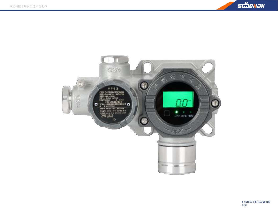
Industrial and Commercial Point-Type Gas Detector
Jinan Benan Technology Development Co., Ltd.
Strip Coating and Plating Production Line Equipment
MCC-SFRE HEAVY INDUSTRY EQUIPMENT CO., LTD.
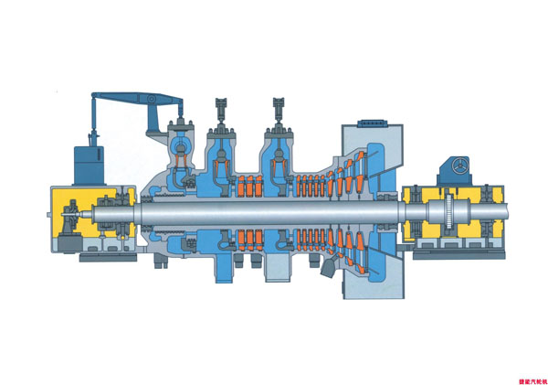

CAP1400 main feedwater flow nozzle flowmeter.
Jiangsu Hongda Instrument Technology Co., LTD.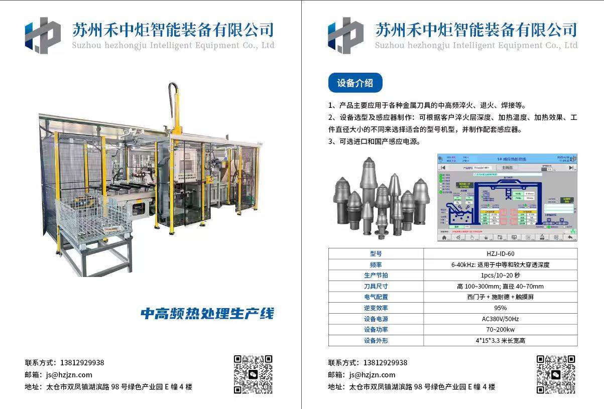
Excavator Bucket Teeth Heat Treatment Production Line
Suzhou Hezhongju Intelligent Equipment Co., Ltd.

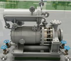
Standard Nozzle Flowmeter
Jinggong Automatic Control Instrument Complete Technology Development Company