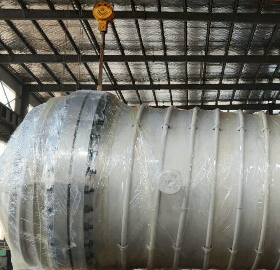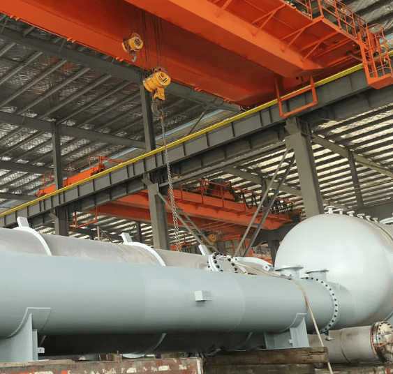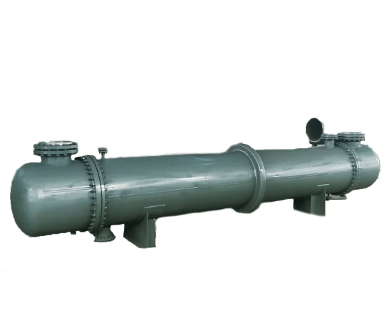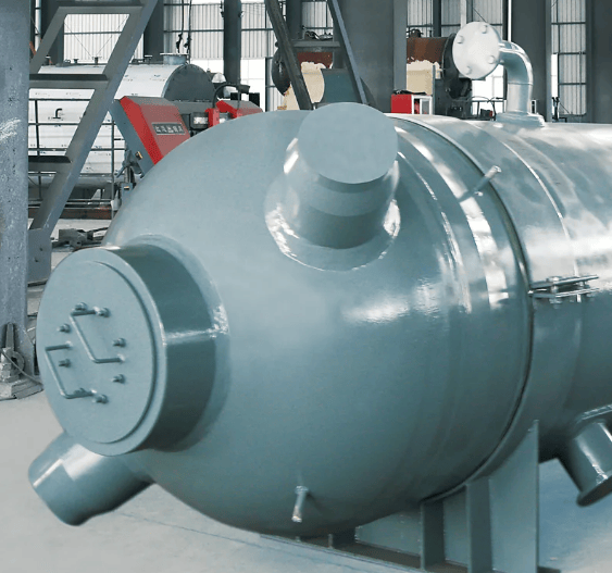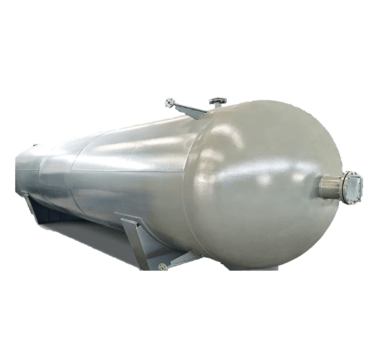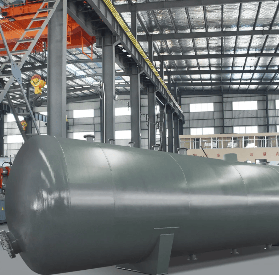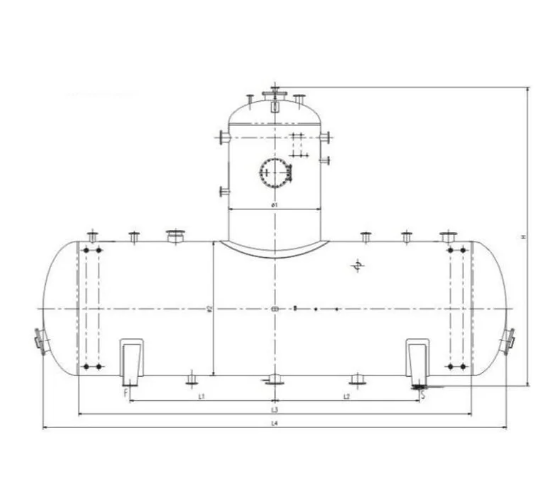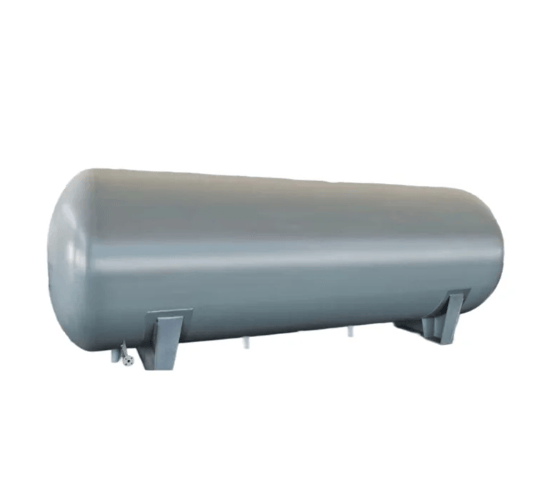
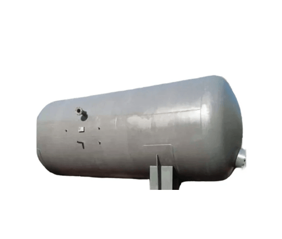


High-pressure thermal deaerators and tower-type rotary membrane deaerators can be used for deaeration in high-parameter boilers. With the increasingly stringent requirements of modern industry for boiler feedwater quality, namely the demand for extremely low absolute oxygen content in feedwater and high relative stability of water quality, the applicability of conventional high-pressure thermal deaerators and rotary membrane deaerators has revealed their limitations due to constraints imposed by their internal structural design.
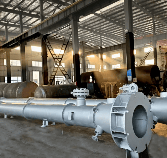
The built-in thermal deaerator fundamentally changes the concept of conventional deaerators in terms of structure, making the deaerator simpler in design, manufacturing, and process operation, with stronger adaptability to variable operating conditions, lower operating costs, reduced investment, and a wide range of applications.
Structural Principle of the Built-in Deaerator:
The built-in thermal deaerator employs a physical method for deaeration, and the deaeration process is carried out in two steps.
(1) Make-up water or condensate is sprayed into the steam space (primary deaeration).
(2) Through steam distribution pipes, steam passes through the water in the tank, carrying dissolved oxygen out of the water to achieve deaeration (secondary deaeration).
The deaeration process of the built-in deaerator is as follows: 
1. Primary Deaeration Zone
Make-up water or condensate is atomized into fine mist-like droplets by spray nozzles, and the flow is regulated according to the water flow rate to ensure that the droplet size remains constant under varying flow conditions. The water droplets are ejected from high-speed nozzles into the steam space within the tank, where they come into contact with steam and are heated, causing the water temperature to rise and the partial pressure of non-condensable gases in the water to gradually decrease. The sprayed water then falls upon striking the tank baffles or tank walls, and is further broken into smaller droplets by the impact.
The residence time of the droplets in the steam space is less than 1 second. In the steam space, the continuous supply of steam ensures a sufficiently high steam partial pressure, while the local partial pressure of non-condensable gases can only be maintained at a very low level. As the droplets pass through the higher-temperature steam, condensation occurs on the surface of the droplets, thereby raising the temperature of the droplets. This heating process is accomplished rapidly thanks to the large contact area of the droplets. After the droplets enter the steam space, the local partial pressure of non-condensable gases in the steam is very low compared to the content of non-condensable gases dissolved in the water. This low local partial pressure, combined with the reduced solubility of non-condensable gases in water caused by the temperature rise, forces the non-condensable gases to separate from the water.
2. Secondary Deaeration Zone
Due to the relatively short residence time of water in the steam space of the spray zone, it may be difficult for the water to achieve the desired deaeration effect. To address this, perforated steam distribution pipes are installed in the lower space of the deaerator storage tank, and the residual non-condensable gases are carried out of the water by the steam discharged from the steam distribution pipes as it passes through the water.
When steam bubbles pass through the water, a phase equilibrium is established between the gas within the steam bubbles and the adjacent dissolved gases, in accordance with Raoult's law. Achieving this equilibrium requires sufficient contact time. For this purpose, the internal structural design of the equipment is arranged to generate smaller bubbles and ensure a sufficiently long travel path through the water, which is accomplished by designing the orifice size, quantity, and arrangement angle on the steam distribution pipes. The second function of the steam distribution pipes is to enable rapid startup of the deaerator, allowing the outlet water quality to meet design requirements in the shortest possible time. Compared with any other steam heating method, the advantage of the steam distribution pipes at the bottom of the tank lies in their ability to achieve thorough deaeration of the water in the tank.
Constant-Flow Nozzle
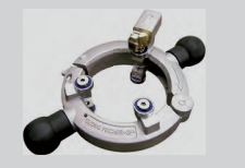
The constant-flow nozzle is a critical component of the built-in deaerator, as it directly affects the quality of the outlet water. The constant-flow nozzle consists of two opposing disc-shaped elastic elements clamped together. When the internal pressure within the nozzle increases, the disc-shaped elastic elements undergo elastic buckling, and water is ejected from the gap between the clamped elements to form a water film. The water film is then broken up and agitated by the serrated structure at the nozzle outlet engagement point, forming fine mist-like droplets. The nozzle cross-section varies with the flow rate, and the flow velocity remains essentially constant within the range of 10% to 110% of the rated nozzle flow, ensuring stable water film atomization.