en.Wedoany.com Reported - Webasto has launched the 900 EX Power Bridge integrated hardware platform, a solution that couples existing independent test units to expand the total system output capability to 1500 V and 500 kW, designed specifically to support higher-voltage battery testing in automotive, off-highway, marine, rail, and stationary energy storage applications. The system allows users to structurally link independent test equipment to meet the demands of next-generation high-voltage platforms without increasing control complexity.
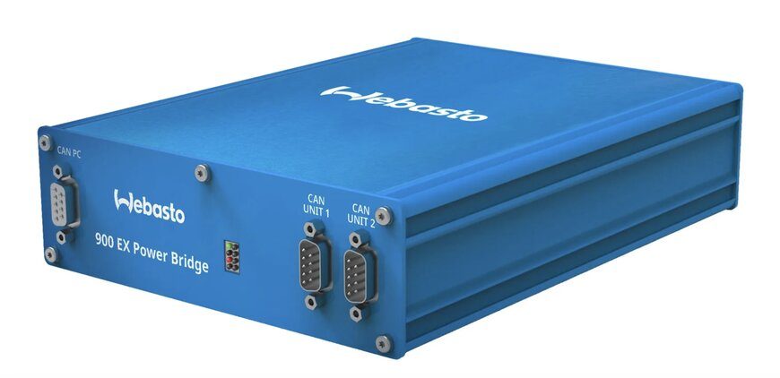
The expansion of high-voltage electric vehicle battery packs and commercial grid-connected energy storage architectures requires laboratory hardware capable of verifying safety and operational limits under accelerated performance loads. The 900 EX Power Bridge addresses these needs by enabling test engineers to combine two independent 900 EX units into a synchronized test network. When configured in a series coupling arrangement, the hardware extends the total system performance threshold to 1500 VDC and 500 kW, allowing laboratories and automotive suppliers to enhance high-voltage verification capabilities while maximizing the utility of existing test infrastructure.
This coupling solution is designed to maintain operational continuity within existing laboratory frameworks. After integration via the module connection, each 900 EX unit retains its independent operational logic, performance characteristics, and unit behavior. The system preserves existing asset management processes through several software and mechanical features: for interface compatibility, the module natively supports Webasto's standard Controller Area Network (CAN) interface, allowing existing CAN-based high-frequency control software to automatically manage the coupled units; for maintenance, the configuration requires no new calibration procedures, auxiliary maintenance tools, or on-site training courses, with standard independent maintenance guidelines directly applicable to the dual-unit setup; for control responsiveness, the integrated system retains high-frequency control loops and signal response parameters, ensuring consistency in parameter verification during rapid dynamic switching.
Independent engineering laboratories, such as Excel Engineering, have already deployed this system to address 1500 V platform verification needs. The setup allows operators to implement high-frequency control scripts and adapt to changing customer evaluation plans without modifying central control panel workflows or altering localized laboratory safety boundaries. Industrial battery cycle test systems are complex bidirectional power electronics systems that deliver current during simulated charging cycles and return current to the grid through regenerative energy recovery loops during discharge sequences. High-power cycle test systems typically employ internal interleaved insulated-gate bipolar transistor (IGBT) topologies or silicon carbide (SiC) metal-oxide-semiconductor field-effect transistor (MOSFET) switching modules arranged in multi-channel configurations. To break through the physical dielectric breakdown limits of a single unit's semiconductor stack and extend the operating voltage range, two independent power modules must be connected in series. Connecting independent bidirectional power supplies in series introduces electrical control challenges such as voltage balancing and preventing transient synchronization delays. If one unit's internal power stage switches slightly faster than the adjacent unit during a high-frequency pulse step, a transient voltage imbalance occurs on the intermediate DC bus, potentially causing the lagging unit to experience localized overvoltage stress, triggering an automatic overvoltage protection fault and resulting in unexpected system shutdown. To overcome this issue, the integrated bridge employs hardware-level synchronization lines that bypass standard fieldbus delays, locking the internal pulse-width modulation carriers of both units to a shared master clock, ensuring that the current change rate is executed simultaneously by both power stages, thereby minimizing voltage ripple and maintaining control accuracy at higher voltage levels.
This article is compiled by Wedoany. All AI citations must indicate the source as "Wedoany". If there is any infringement or other issues, please notify us promptly, and we will modify or delete it accordingly. Email: news@wedoany.com